Contact for a portable electronic device

a technology of electronic devices and contacts, applied in the direction of coupling device connections, substation equipment, transmission, etc., can solve the problems of loss of stored information, damage to electronic components of electronic devices, and the portability of electronic devices falling on the ground or experiencing a large external impa

Inactive Publication Date: 2007-05-22
LG ELECTRONICS INC
View PDF12 Cites 23 Cited by
  • Summary
  • Abstract
  • Description
  • Claims
  • Application Information

AI Technical Summary

Benefits of technology

[0010]The present invention provides a contact for a portable electronic device to prevent breaking electric contact between a battery and a component of the portable electric device upon an external impact.

Problems solved by technology

While carrying the portable electronic device, the portable electronic device may fall on the ground or experience a large external impact.
The momentary break in power to the electronic device 10 may result in a loss of stored information, and in some cases may damage the electronic components of the electronic device 10.

Method used


Image

  • Contact for a portable electronic device
  • Contact for a portable electronic device
  • Contact for a portable electronic device

Examples


first embodiment

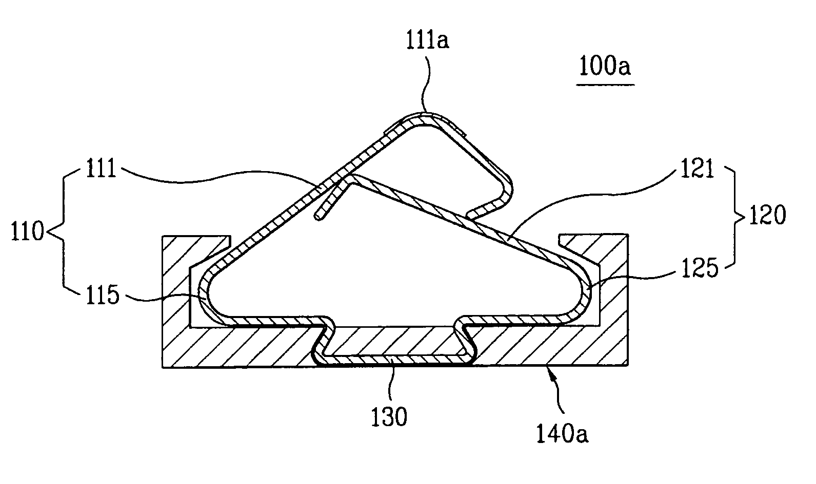
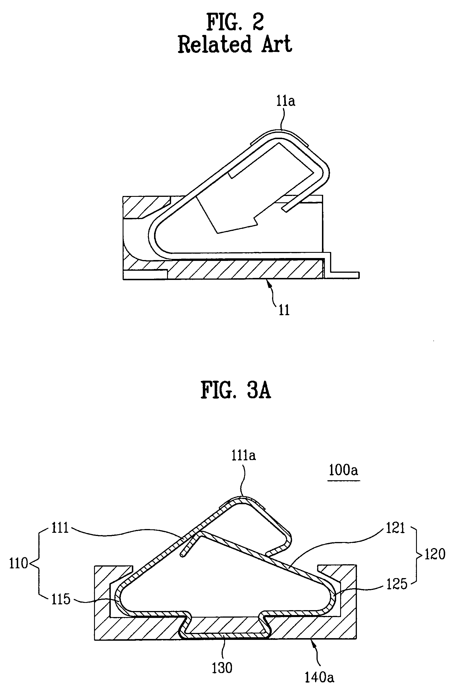
[0033]FIGS. 3A and 3B depict the contact 100a of the invention. The contact 100a comprises a first contact 110 having a contact portion 111 and a first elastic portion 115. A second contact 120 is provided having a support portion 121, a second elastic portion 120, and a member having a connection portion 130 within a contact housing 140a.

[0034]The first contact 110 elastically presses down against a mating contact, for example, a flat surface. The contact portion 111 has a curved portion with an elongated ridge 111a outwardly projecting from the contact 100a. The elongated ridge 111a pushes, for example, on a small area with a high pressure on the mating contact, resulting in an end of the contact portion 111 being pushed inwardly. The first elastic portion 115 provides an elastic force along curved portion projecting outward from the contact portion 111 for pushing the contact portion 111 onto a mating contact.

[0035]In one example, a front or an upper surface of the first contact...

second embodiment

[0047]FIG. 4 illustrates a present invention. In this embodiment, the contact 100b providing a first contact 110 and a second contact 120 fixedly secured to a contact housing 140b. A member for securely mounting the first contact 110 and the second contact 120 on the battery or the body includes a contact housing 140b. The first contact 110 and the second contact 120 are fixedly secured to the contact housing 140b.

[0048]The first contact 110 comprises a contact portion 111, a first elastic portion 115, and a first securing portion 117. The second contact 120 comprises a support portion 121, a second elastic portion 125, and a second securing portion 127. The structures of the contact portion 111, the first elastic portion 115, the support portion 121, and the second elastic portion are described in FIGS. 3A, 3B, and 3C.

[0049]The first securing portion 117 of the first contact 110 extends from the first elastic portion 115, and is secured to the contact housing 140b. The second secu...


PUM


Abstract

An apparatus is disclosed for a contact for a portable electronic device. The contact comprises a first contact for maintaining elastic connectivity with the mating contact, a second contact for providing an elastic force to push the first contact toward the mating contact to support the first contact, and a member for mounting the first contact and the second contact.

Description

CROSS-REFERENCE TO RELATED APPLICATIONS[0001]Pursuant to 35 U.S.C. § 119(a), this application claims the benefit of earlier filing date and right of priority to Korean Application No. 10-2004-00051614, filed on Jul. 2, 2004, the contents of which are hereby incorporated by reference herein in its entirety.BACKGROUND OF THE INVENTION[0002]1. Field of the Invention[0003]The present invention relates to contacts, and more particularly, to a contact for a portable electronic device for connecting a battery and a component, or components in the portable electronic device, such as a cellular phone.[0004]2. Description of the Related Art[0005]Portable electronic devices, such as cellular phones, portable video and / or audio recorders, such as MP3 (MPEG Audio Layer-3) players, compact disc players, and cassette tape players, personal digital assistant (PDA), and laptop computers are popular among users. Portable electronic devices require an electrical power source available during transport...

Claims


Application Information

Patent Timeline
Patent Type & Authority Patents(United States)
IPC IPC(8): H01R4/48
CPCH01R13/2492H04B1/3816H04B1/3883H04M1/0262H01R13/2421H01R2201/16H04B1/40
Inventor JEONG, YI SEON
Owner LG ELECTRONICS INC
Why Eureka
Try Eureka