Magnetic component having a bobbin structure with integrated winding

a technology of bobbin structure and magnetic component, which is applied in the direction of transformer/inductance details, coils, electrical apparatus, etc., can solve the problems of component failure, component malfunction or failure, undesired performance fluctuations or component failure, and achieve the effect of reducing the time required for production

Inactive Publication Date: 2011-10-04
UNIVERSAL LIGHTING TECHNOLOGIES
View PDF19 Cites 15 Cited by
  • Summary
  • Abstract
  • Description
  • Claims
  • Application Information

AI Technical Summary

Benefits of technology

[0015]It is another object of the present invention to provide a bobbin structure having a single-turn conductive winding embedded in the bobbin body for reducing the time required for production of a bobbin-wound magnetic component.
[0016]It is yet another object of the present invention to provide an improved magnetic component having a bobbin structure with an insulated winding for preventing electrical contact between separate windings.

Problems solved by technology

Even a minor deviation from the proper single-turn winding placement can result in component failure.
As such, the single-turn winding may shift along the exterior of the bobbin structure during use, resulting in component malfunction or failure.
In the prior art, the bobbin structure and the insertable single-turn winding are separate pieces, and the single-turn winding may shift relative to the bobbin structure during use, causing undesired performance fluctuations or component failure.
Also, the two-piece design of the prior art adds complexity to the design of the bobbin structure, requiring multiple components.
However, conventional bobbin-wound components allow partially exposed regions of the windings to occasionally form an undesired electrical contact between the windings.
Electrical contact between windings can cause component failure.
The rate of production of bobbin-wound components having a single-turn winding is often limited by the time required for the winding machine to properly position the single-turn winding onto the bobbin structure.
Precise positioning of the single-turn winding generally increases the overall component winding time and, thus, limits the overall rate of bobbin-wound component production.

Method used


Image

  • Magnetic component having a bobbin structure with integrated winding
  • Magnetic component having a bobbin structure with integrated winding
  • Magnetic component having a bobbin structure with integrated winding

Examples


Embodiment Construction

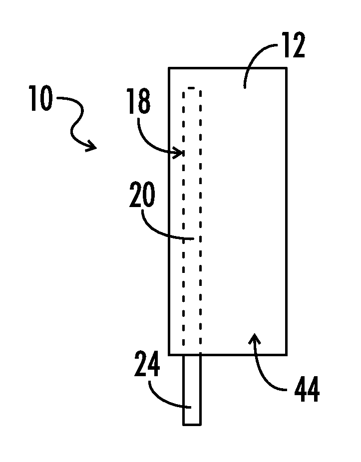
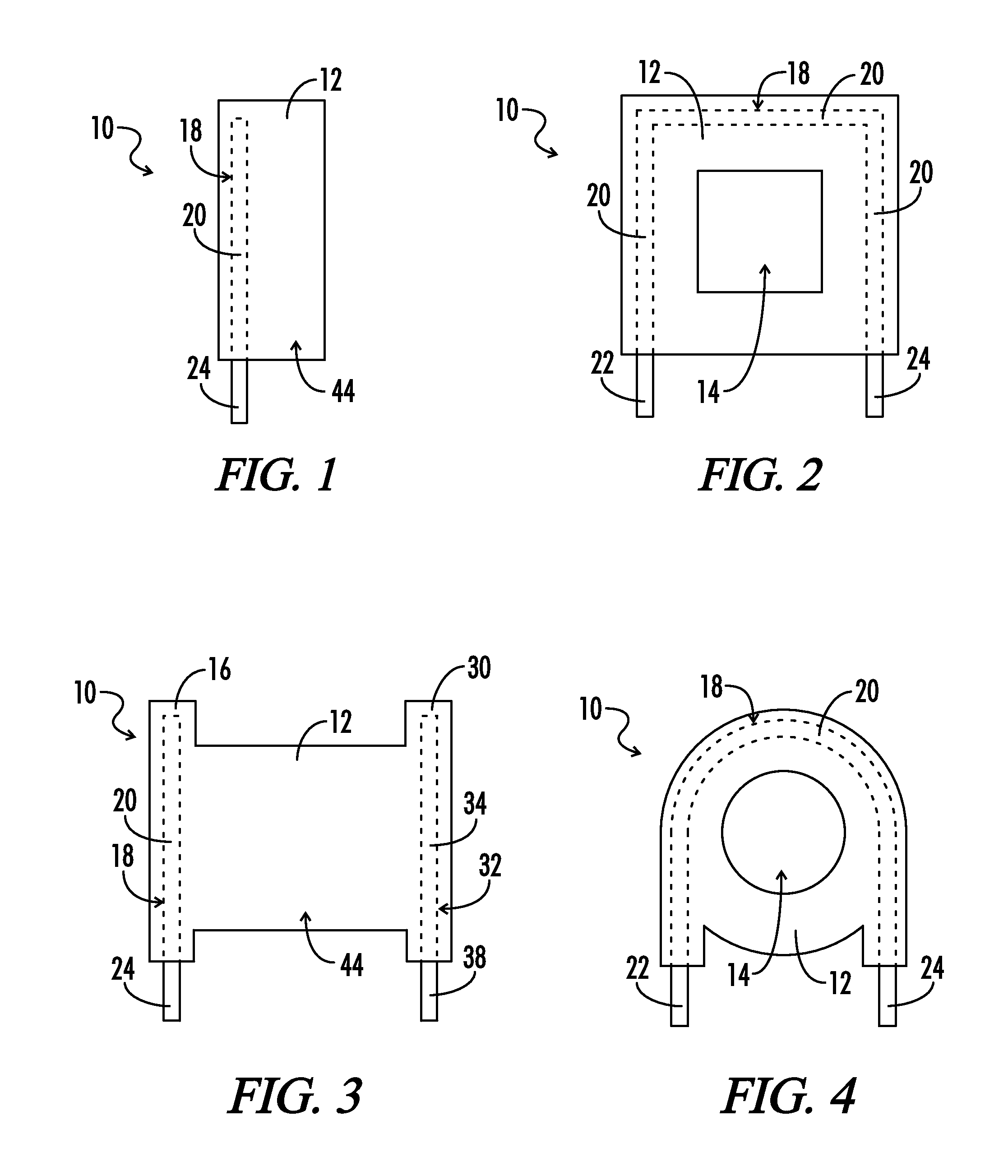
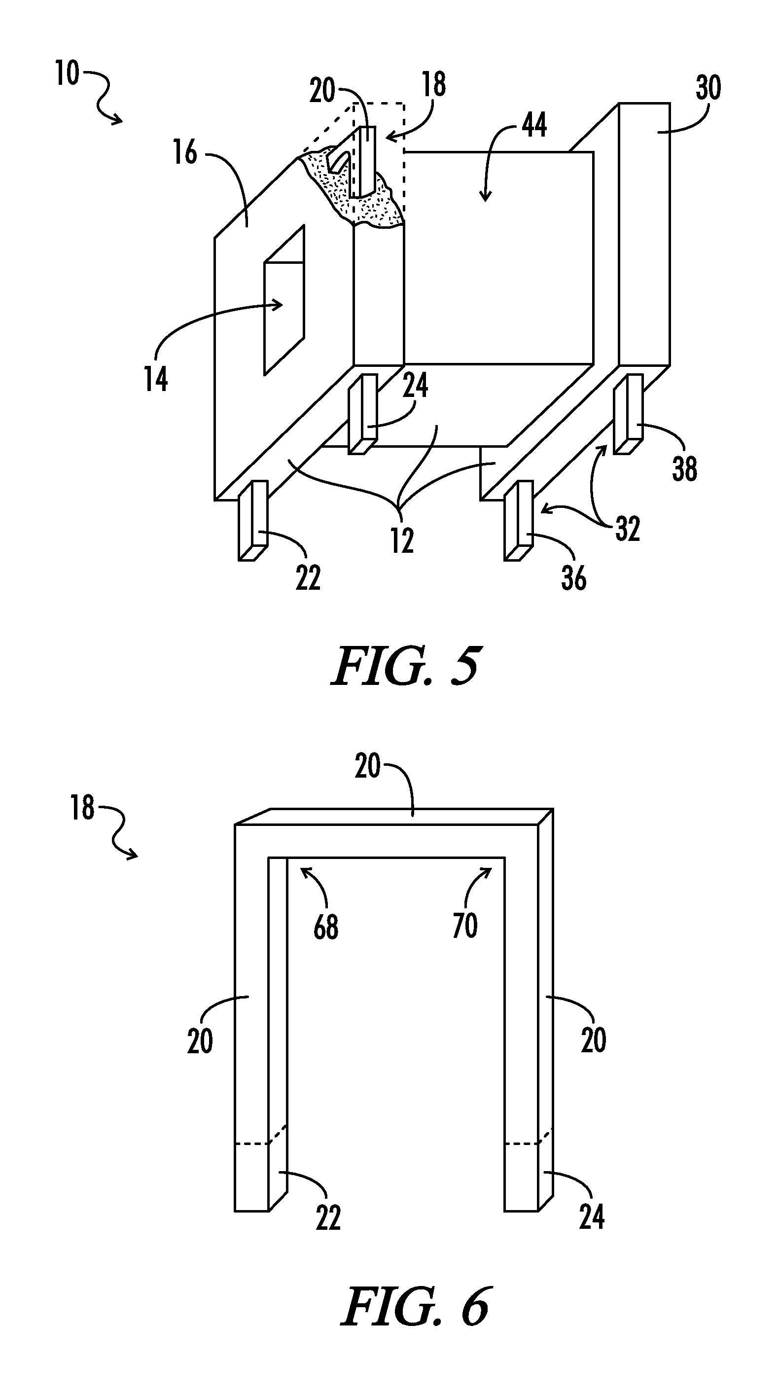
[0029]Referring now to FIG. 1 and FIG. 2, there is shown generally one embodiment of a bobbin structure 10 in accordance with the present invention. The bobbin structure 10 includes a bobbin body 12, a winding region 44 positioned on the bobbin body 12, and a first winding 18 embedded in the bobbin body 12. The first winding 18 includes a winding body 20, a first terminal end 22 and a second terminal end 24, as shown in FIG. 2. The first winding 18 is generally made of an electrically conductive material, and the bobbin body 12 is generally made of an electrically insulative material. A terminal end is defined as a region of a winding that extends from the bobbin body 12 for connection to an electric circuit. The first terminal end 22 and the second terminal end 24 are not embedded in the bobbin body 12. In one embodiment, the winding body 20 of the first winding 18 is completely embedded in the bobbin body 12. Also shown in FIG. 2, the bobbin body 12 includes a hollow interior cavi...


PUM

PropertyMeasurementUnit
structureaaaaaaaaaa
shapeaaaaaaaaaa
conductiveaaaaaaaaaa

Abstract

A magnetic component has a bobbin structure for winding a conductive material. The bobbin structure includes a bobbin body having a first winding embedded in the bobbin body. The first winding is made of a conductive material. The first winding includes a winding body and two terminal ends. The terminal ends protrude from the bobbin body for connection to a circuit. The winding body of the first winding is embedded inside the bobbin body. Alternatively, the first conductive winding is embedded in a bobbin flange included on the bobbin body. The bobbin structure generally includes a hollow interior cavity shaped for inserting a ferrite core.

Description

[0001]A portion of the disclosure of this patent document contains material that is subject to copyright protection. The copyright owner has no objection to the reproduction of the patent document or the patent disclosure, as it appears in the U.S. Patent and Trademark Office patent file or records, but otherwise reserves all copyright rights whatsoever.CROSS-REFERENCES TO RELATED APPLICATIONS[0002]Not applicable.BACKGROUND OF THE INVENTION[0003]The present invention relates generally to a magnetic component having at least one conductive winding and more specifically to a magnetic component having a bobbin structure for winding a conductive coil. More particularly the present invention relates to a bobbin structure having a molded bobbin body including a first conductive winding embedded therein.[0004]Magnetic components utilizing a bobbin structure for positioning a conductive winding are known in the prior art. These components, including certain transformers and inductors, are c...

Claims


Application Information

Patent Timeline
Patent Type & Authority Patents(United States)
IPC IPC(8): H01F27/30H01F27/29
CPCH01F5/02H01F27/306H01F2005/022
Inventor FOLKER, DONALDLEBLANC, MIKE
Owner UNIVERSAL LIGHTING TECHNOLOGIES
Why Eureka
Try Eureka