Photovoltaic insulating glazing

Inactive Publication Date: 2010-11-16
GLASWERKE ARNOLD
View PDF38 Cites 11 Cited by
  • Summary
  • Abstract
  • Description
  • Claims
  • Application Information

AI Technical Summary

Benefits of technology

[0031]Such a block can also prevent crushing of the connecting cables between substructure and glass during installation.
[0032]A block of this type may comprise grooved recesses along the glass edge to receive the cable, which offer the additional advantage of increased sealing material coverage in the regio

Problems solved by technology

In particular, processing of photovoltaic modules whose electric connections, the so-called “contact strips”, exit the photovoltaic module through bores on the rear-side of the module cover ca

Method used


Image

  • Photovoltaic insulating glazing
  • Photovoltaic insulating glazing
  • Photovoltaic insulating glazing

Examples


Embodiment Construction

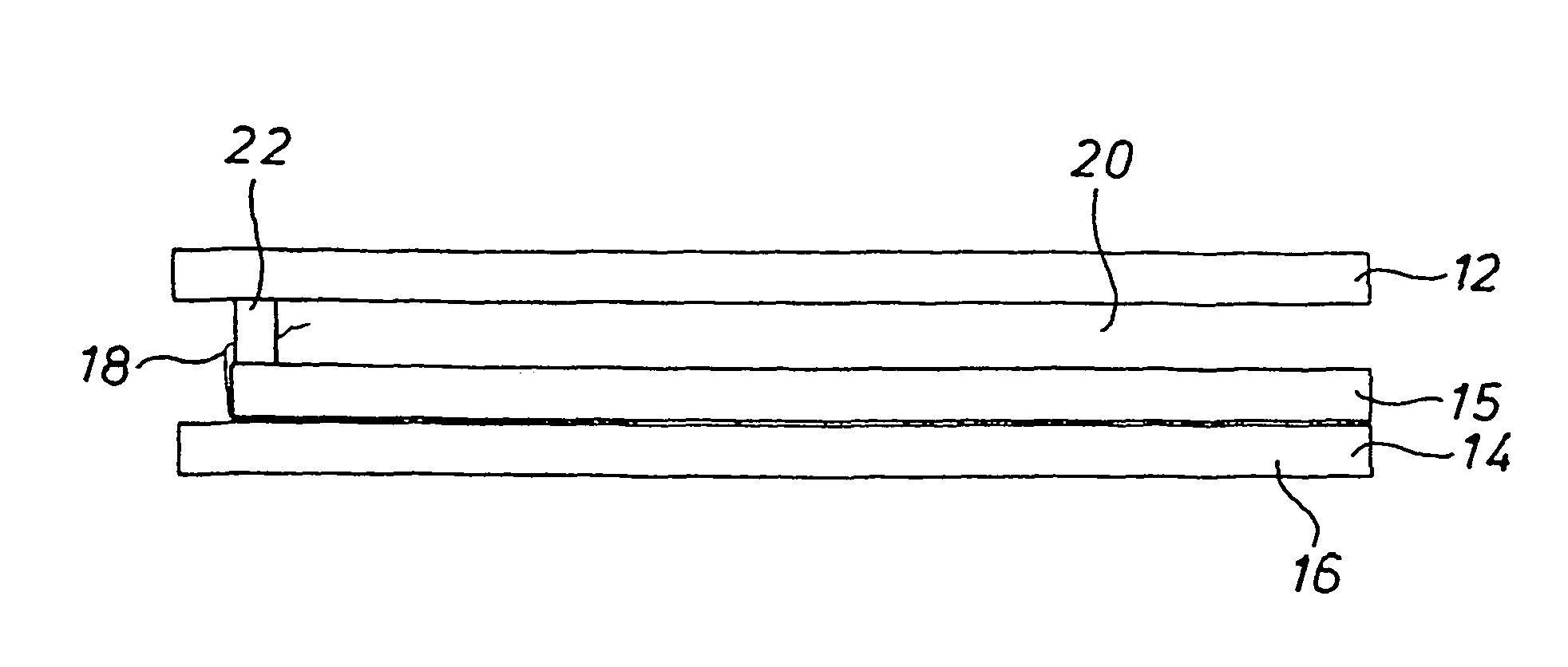
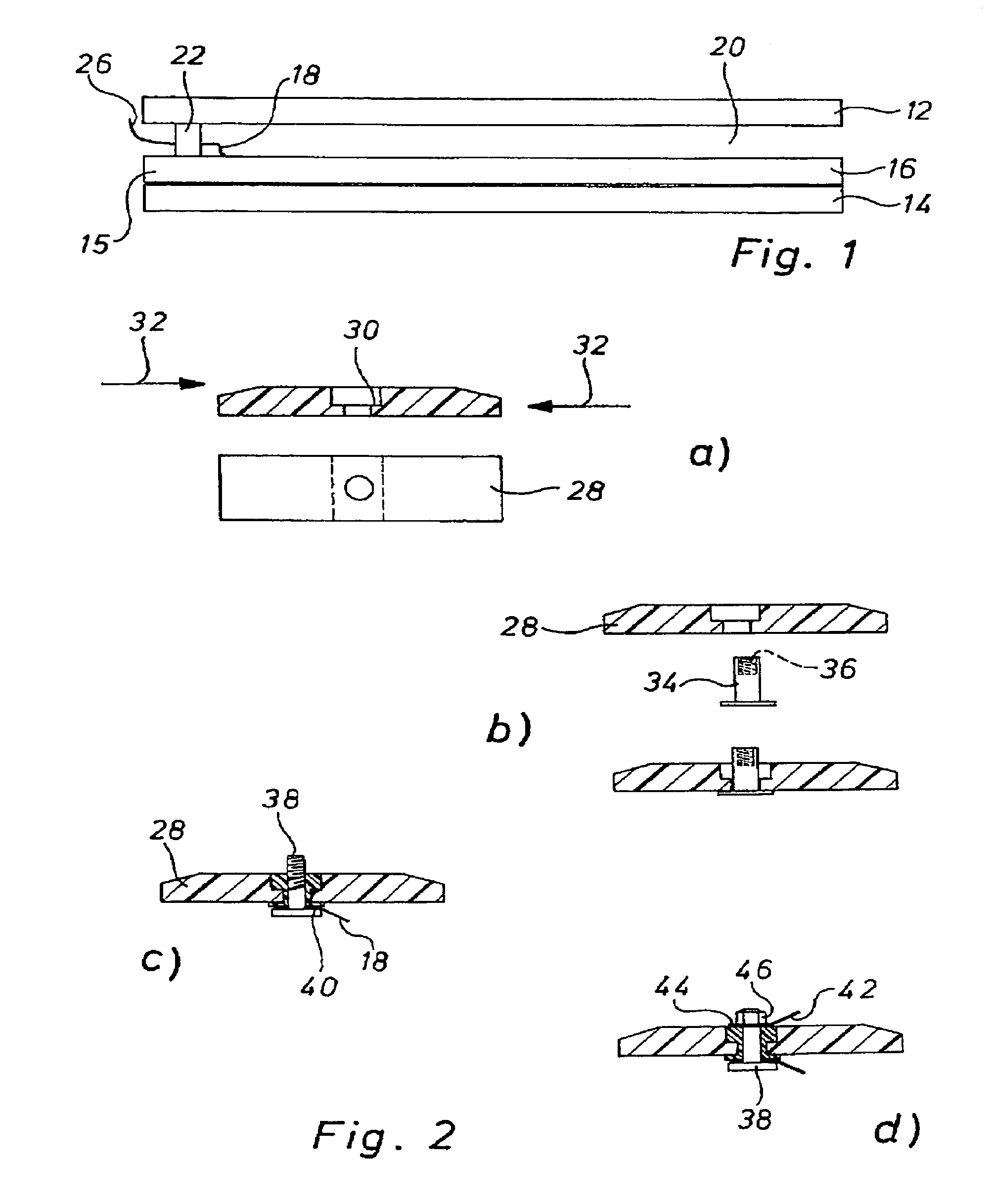
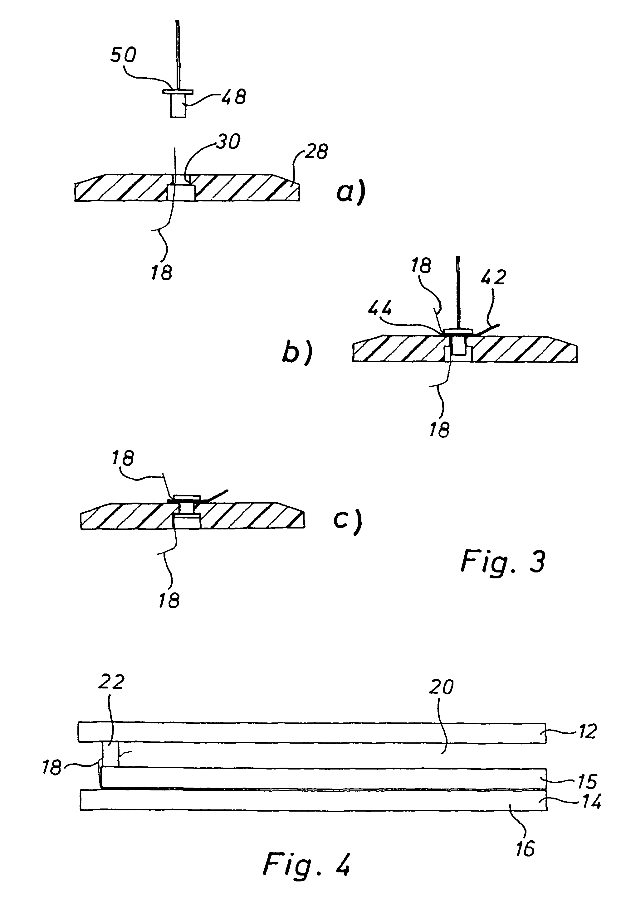
[0039]FIG. 1 shows an insulating glazing which consists of two external glass panes 12 and 14. The pane 14 forms the outer cover of a photovoltaic module 16. The pane 15 forms the inner cover. Solar cells are disposed between the panes 14, 15.

[0040]The photovoltaic module 16 has a contact strip 18 to provide an electric connection. The contact strip 18 is thereby guided in the space 20 between the panes through a bore in the inner cover 15.

[0041]A conventional spacer 22 is provided to define a space 20 between the pane 15 and glass pane 12, which has an insulating function and by means of which the electric connection can be guided through the space 20 between the panes to the outside where it can contact an electric connecting element 26, in most cases an external cable. The space 20 between the panes is filled with gas, as is typical for insulating glazing. The electric connection must therefore be gas and vapor-tight.

[0042]The spacers 22 comprise of hollow aluminium, shaped eleme...


PUM

PropertyMeasurementUnit
Lengthaaaaaaaaaa
Electrical conductoraaaaaaaaaa
Elasticityaaaaaaaaaa

Abstract

The invention relates to a photovoltaic insulating glazing comprising a multi-layer glazing with a photovoltaic module. The glazing is further characterized in that two contact strips for contacting the photovoltaic module are led out from an intermediate space between the glass layers and a spacer spaces the glass layers apart, thereby forming the intermediate space.

Description

[0001]This application is the national stage of PCT / EP02 / 10620 filed on Sep. 20, 2002 and also claims Paris Convention priority of DE 101 46 498.3 filed on Sep. 21, 2001.BACKGROUND OF THE INVENTION[0002]The invention concerns a photovoltaic insulating glazing comprising a multi-layer glazing with a photovoltaic module, wherein contact strips contact the photovoltaic module and are led out from the photovoltaic module, and with a spacer, formed e.g. as a shaped bar, which spaces apart glass layers to form an intermediate space.[0003]Photovoltaic modules are integrated into insulating glazing via a glass layer e.g. of a double glass structure, into or onto which the solar cells are embedded or disposed. The module generally constitutes one layer of the insulating glazing. The other layer is formed by a glass pane. An intermediate space is provided between the sheet of glass and the photovoltaic module which can be filled with gas to effect an insulating glazing. The invention also con...

Claims


Application Information

Patent Timeline
IPC IPC(8): H02N6/00H01L25/04H01L31/04H01J5/02E06B3/24H01L31/00C03C27/06H01L31/02H01L31/042H01L31/048
CPCH01L31/02008H01L31/0488Y02E10/50Y10T428/24777Y10T428/22Y10T428/1059C09K2323/05
Inventor SCHMIDT, CHRISTOPH
Owner GLASWERKE ARNOLD
Why Eureka
Try Eureka