Flowline clamp connector

a technology of flowline and connector, which is applied in the direction of hose connection, cable termination, mechanical equipment, etc., can solve the problems of hammer unions that could shatter or break due to blows, explosions, and work injuries, and achieve the effect of avoiding damage to elastomeric seals

Active Publication Date: 2007-04-17
SPM OIL & GAS INC
View PDF6 Cites 40 Cited by
  • Summary
  • Abstract
  • Description
  • Claims
  • Application Information

AI Technical Summary

Benefits of technology

[0009]In one embodiment, each recess has a cylindrical portion adjacent its end. The elastomeric seals seal against the cylindrical portions of the recesses. Further, the contact of the legs of the ring with the conical portions of the recesses forms secondary metal-to-metal seals to prevent extrusion of the elastomeric seals into the conical portions of the recesses. Preferably the legs of the ring are sized to create an interference contact with the conical portions of the recesses. The dimensions are selected so that the legs of the ring undergo elastic deformation when the connector is made up. During insertion of the ring, the elastomeric seals clear the conical portions of the recesses and only engage the cylindrical portions to avoid damage to the elastomeric seals.

Problems solved by technology

While these hammer union systems work well, there are disadvantages.
A worker might sustain an injury while lifting the components and delivering blows with a hammer.
In very cold climates, the hammer union could shatter or break due to the blows.
Sparks can be created by delivering the blows, which could create an explosion if any combustible gas has leaked in the vicinity.
The task of connecting the components with a hammer union is time consuming.
This type of service flowline avoids the disadvantage of hammer union but is not in wide use.
However, the high pressure ratings mandate a certain amount of support metal and still must be maintained.

Method used


Image

  • Flowline clamp connector
  • Flowline clamp connector
  • Flowline clamp connector

Examples


Embodiment Construction

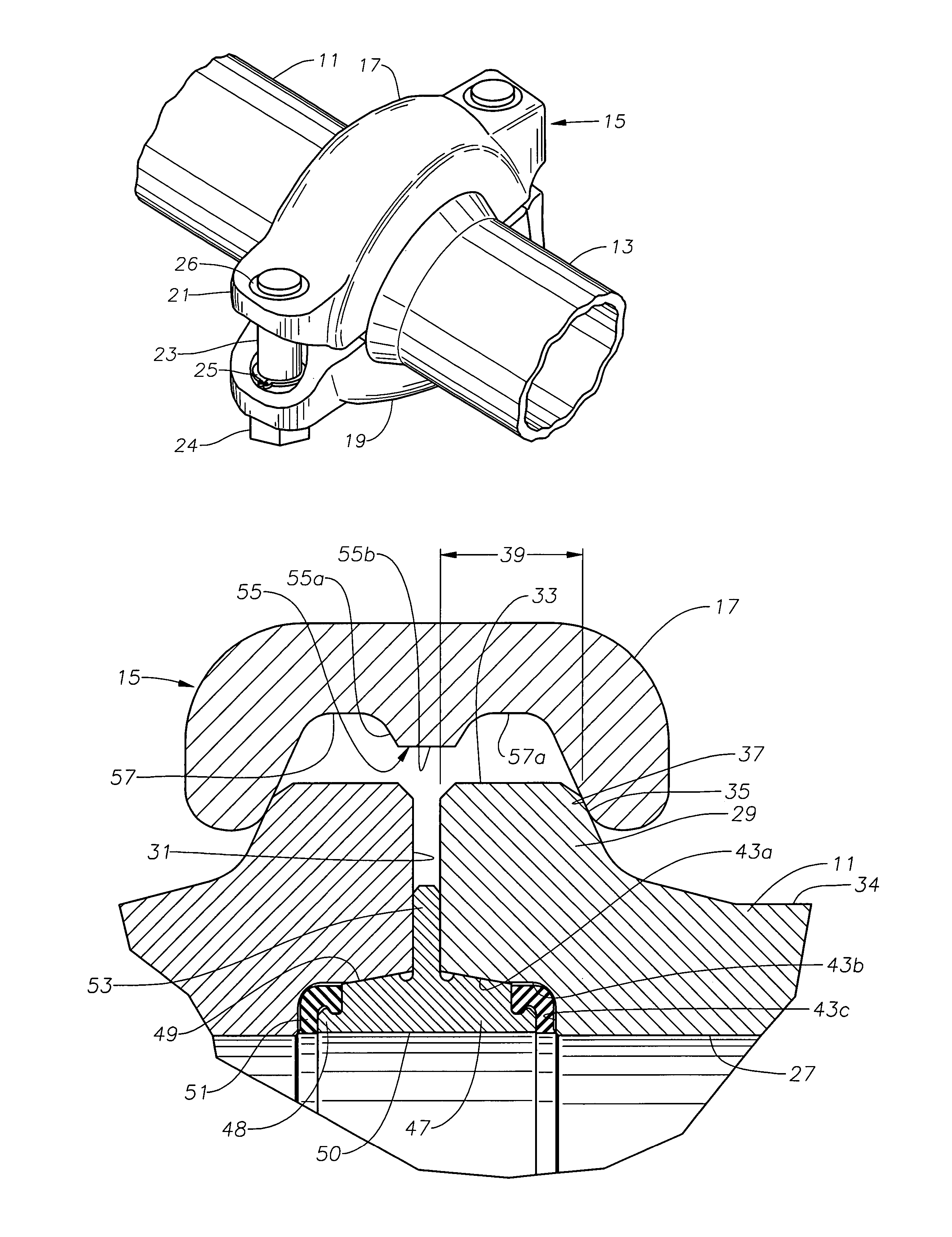
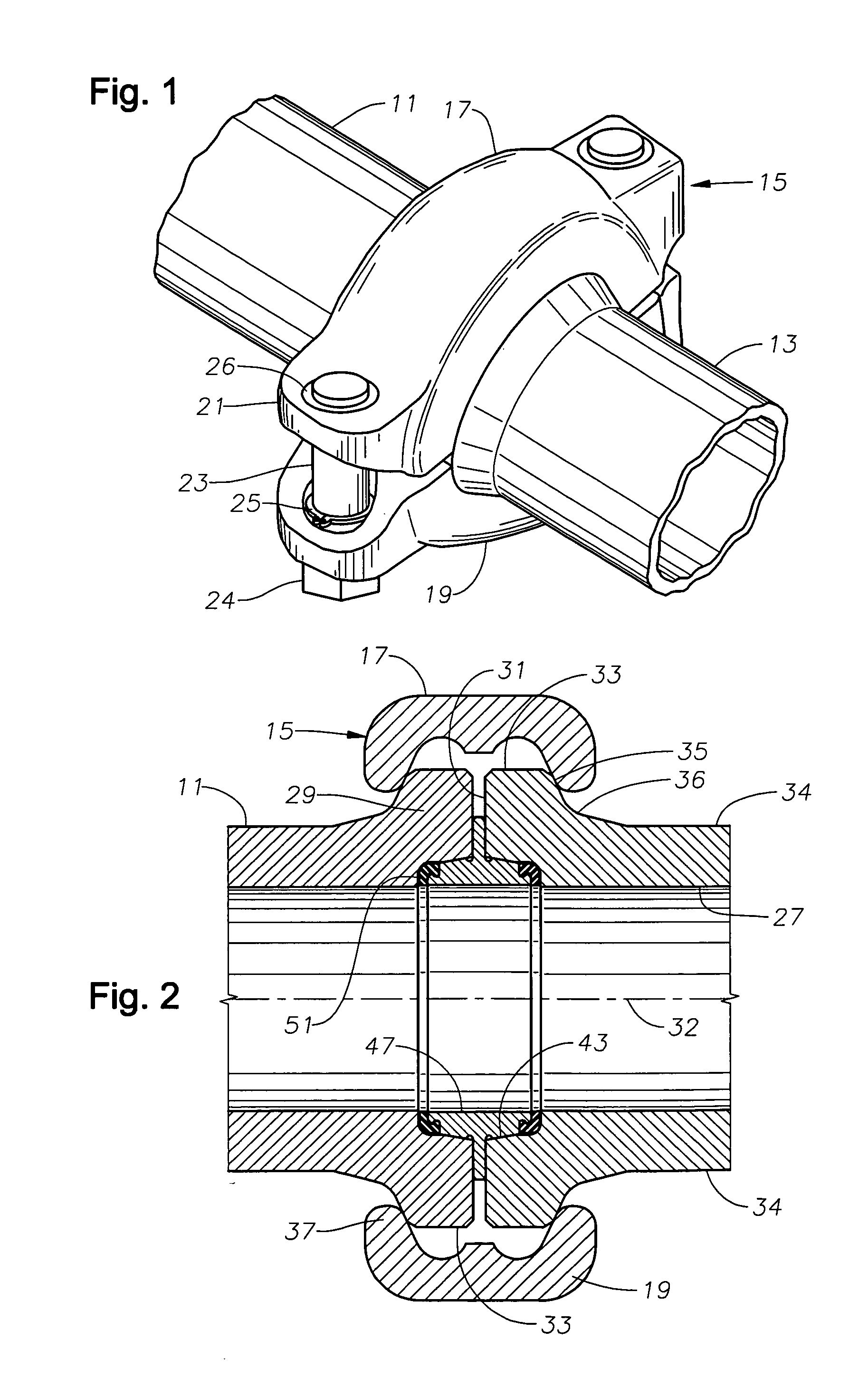
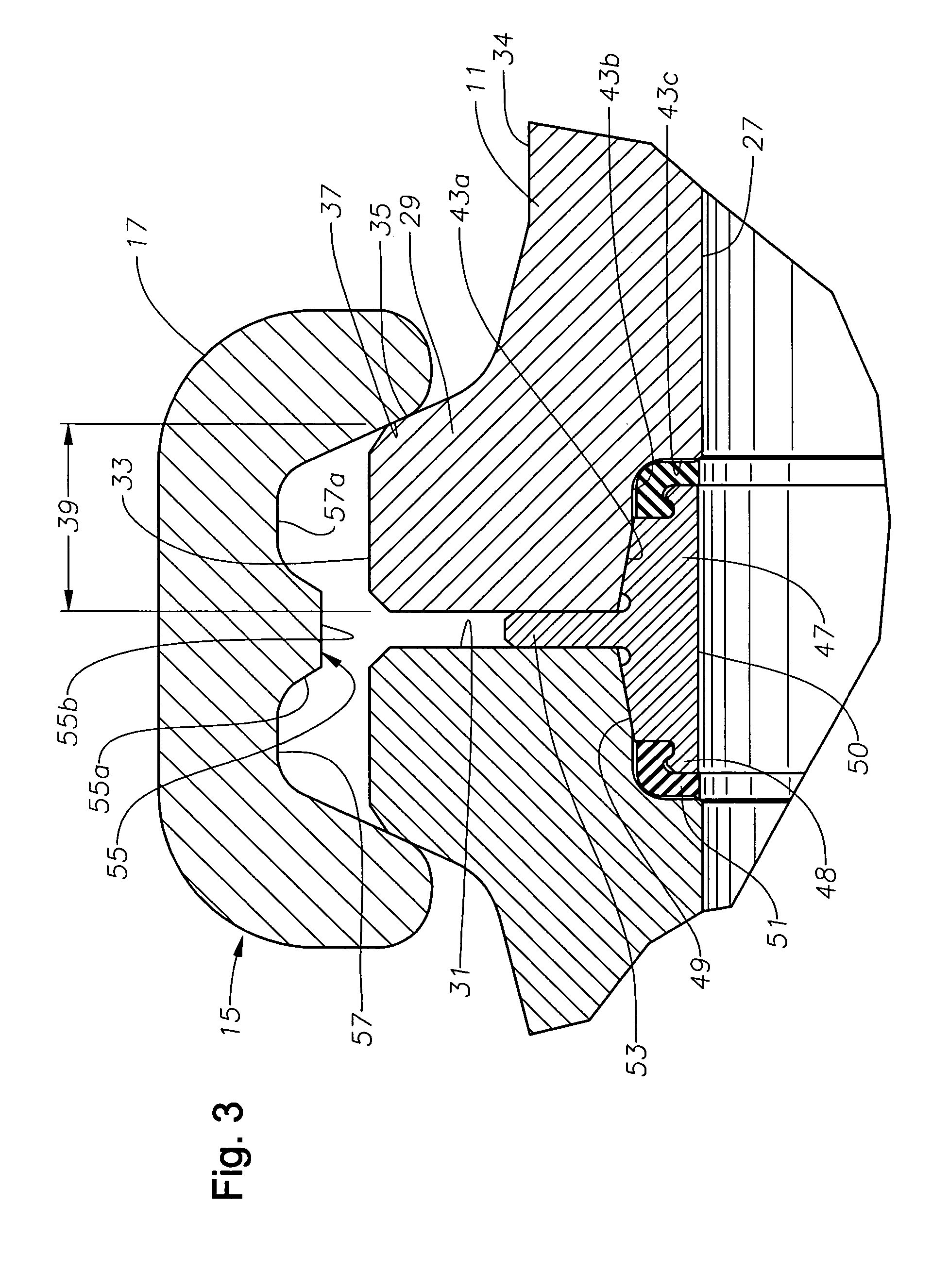
[0014]Referring to FIG. 1, two tubular members 11, 13 are shown connected together by a clamp connector 15. Tubular members 11 are conduits that are utilized in oil and gas well service operations. In typical well service operations, the operator brings high capacity pumps to a well site to pump well fluids into the well for various purposes, such as cementing, fracing, acidizing and the like. A number of tubular members 11 are connected to each other to form temporary flowlines from the pumping equipment to the well. Tubular members 11 comprise lengths of straight pipe, tees, ells, adapters, valve ends and the like. The lengths of straight pipe typically range from a few feet to 20 feet, and inner diameters usually are from 2 inches to 4 inches. Connectors 15 allow tubular members 11 to be quickly made up and disassembled. Tubular members 11 must be able to sustain high pressures, in some cases 15,000 psi to 20,000 psi.

[0015]Connector 15 is a clamp assembly having two halves or sem...


PUM


Abstract

A flowline connection assembly connects first and second tubular members to each other. Each tubular member has an external flange on its end. A conical recess is formed in the bore at the end of each of the tubular members. A metal ring has a pair of legs extending in opposite axial directions, each of the legs having a conical outer surface that engages one of the conical recesses. Each ring has an elastomeric seal that seals the recess. A clamp has cam surfaces that engage the flanges and pull the tubular members axially toward each other.

Description

CROSS-REFERENCE TO RELATED APPLICATION[0001]This application claims priority to provisional application Ser. No. 60 / 566,264, filed Apr. 29, 2004.FIELD OF THE INVENTION[0002]This invention relates in general to oilfield pipe connectors, and in particular to a clamp-type connector for connecting flowlines for well service operations.BACKGROUND OF THE INVENTION[0003]In some oil field service operations, such as hydraulic fracturing, cementing, acidizing and the like, high pressure fluids are pumped down the well. In some cases, the fluid pressures may be in excess of 15,000 psi. Typically, an operator brings high pressure pumping equipment to the well site and installs temporary service flowlines from the high pressure pumps to the wellhead. Because high volumes of fluid may also be needed, a number of pumping units may be connected together at one well site.[0004]The temporary flowline components include joints or sections of steel pipe of differing lengths, various junctions, valves,...

Claims


Application Information

Patent Timeline
Patent Type & Authority Patents(United States)
IPC IPC(8): F16L17/00F16L19/00F16L19/025F16L19/03F16L19/04F16L19/065F16L21/06F16L23/028F16L23/08F16L23/18F16L35/00
CPCF16L21/065F16L23/08Y10S285/917F16L23/18
Inventor MATZNER, MARK D.
Owner SPM OIL & GAS INC
Why Eureka
Try Eureka