Anti-extrusion apparatus and method

a technology of extrusion apparatus and nozzle, which is applied in the direction of fluid removal, sealing/packing, borehole/well accessories, etc., can solve the problems of undeformable deformation of deformable parts and unsatisfactory extrusion of deformable parts, and achieve the effect of reducing the space width

Inactive Publication Date: 2005-01-11
SCHLUMBERGER TECH CORP
View PDF25 Cites 42 Cited by
  • Summary
  • Abstract
  • Description
  • Claims
  • Application Information

AI Technical Summary

Benefits of technology

In accordance with the present invention, certain embodiments involve an apparatus that is useful for discouraging the extrusion of a deformable member of a device into a space located on at least one side of the deformable member when the device is disposed within a borehole, the deformable member extending between the device and borehole wall. The apparatus includes an annular expandable member disposed upon the device and movable between at least one radially non-expanded position and at least one radially expanded position. In a radially expanded position, the annular expandable member reduces the width of the space on at least one side of the deformable member around the circumference of the device, has a continuous outer surface proximate to the deformable member and assists in asserting forces upon the deformable member to maintain the deformable member in engagement with the borehole wall. When the annular expandable member is in a radially non-expanded position, the device is deliverable into and removable from the borehole without obstruction caused by the annular expandable member. In these embodiments, the annular expandable member is redeployable.
Various embodiments of the invention involve an anti-extrusion apparatus useful for reducing the width of an extrusion gap adjacent to a seal member of a downhole device deployed in a borehole, the seal member extending between the downhole device and the borehole wall. The anti-extrusion apparatus includes a redeployable spring-acting member disposed upon the downhole device, the spring-acting member being movable between a radially non-expanded position and a radially expanded position. In the radially expanded position, the spring-acting member reduces the width of the extrusion gap on at least one side of the seal member around the circumference of the downhole device and assists in imparting forces upon the seal member to maintain the seal member in engagement with the borehole wall. In the radially non-expanded position, the spring-acting member is movable within and from the borehole without obstructing movement of the downhole device.
Certain embodiments of the invention involve a downhole tool capable of sealing an annulus formed between the downhole tool and a borehole wall in the presence of a pressure differential in the annulus. The downhole tool includes an inner mandrel deployable into the borehole, at least one elastomeric member, and at least one annular expandable member carried upon the inner mandrel. The elastomeric member is extendable from the downhole tool and sealingly engageable with the borehole wall. The annular expandable member is extendable into the annulus around the circumference of the downhole tool, reducing the width of the annulus proximate to the elastomeric member to discourage extrusion thereof into the annulus. The annular expandable member is also capable of assisting in asserting forces upon the at least one elastomeric member to maintain the at least one elastomeric member in sealing engagement with the borehole wall. The annular expandable member is further capable of being retracted from the annulus to allow movement of the downhole tool within and from the borehole, and the annular expandable member is redeployable.
Some embodiments of the invention involve a method for discouraging the extrusion of a seal member of a device into an annulus formed between the device and the wall of a borehole, the seal member extendable from the device across the annulus and sealingly engageable with the borehole wall, the device also carrying an annular expandable member. The method includes applying compressive force to the annular expandable member, causing the annular expandable member to extend into and reduce the width of the annulus on at least one side of the seal member around the circumference of the device. The annular expandable member asserts force upon the seal member to assist in maintaining the seal member in engagement with the borehole wall. Compressive force is removed from the annular expandable member, causing the annular expandable member to retract from the annulus and allow movement of the device within and out of the borehole, and enabling redeployment of the annular expandable member and seal member. If desired, the device may be repositioned in the same or another borehole. The seal member and annular expandable member may be redeployed.

Problems solved by technology

In such instances, the deformable member may be undesirably forced or extruded into the open annulus adjacent to the deformable member, such as when subject to a differential pressure.
Extrusion of the deformable member may not be desirable, such as when it causes the deformable member to become damaged or lose its seal.

Method used


Image

  • Anti-extrusion apparatus and method
  • Anti-extrusion apparatus and method
  • Anti-extrusion apparatus and method

Examples


example expandable

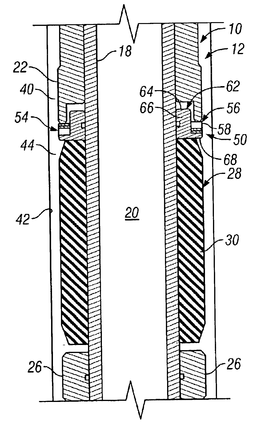
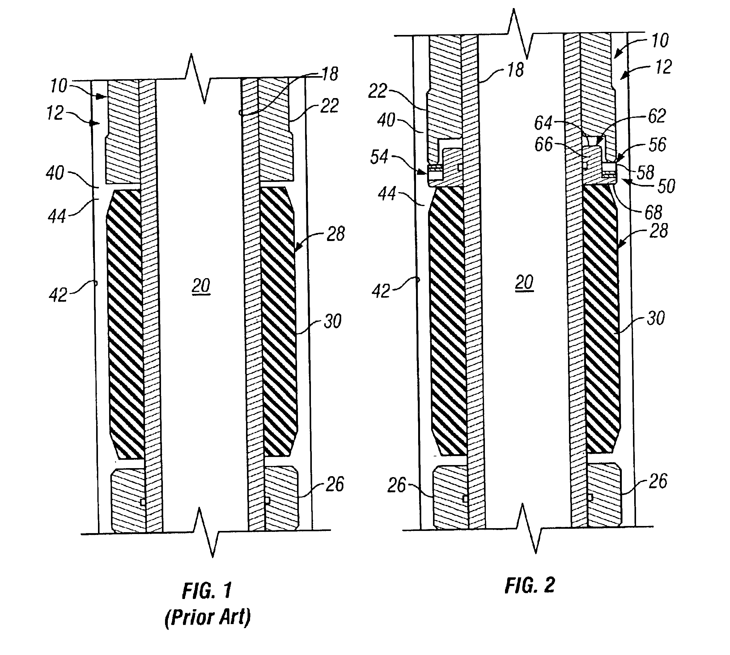
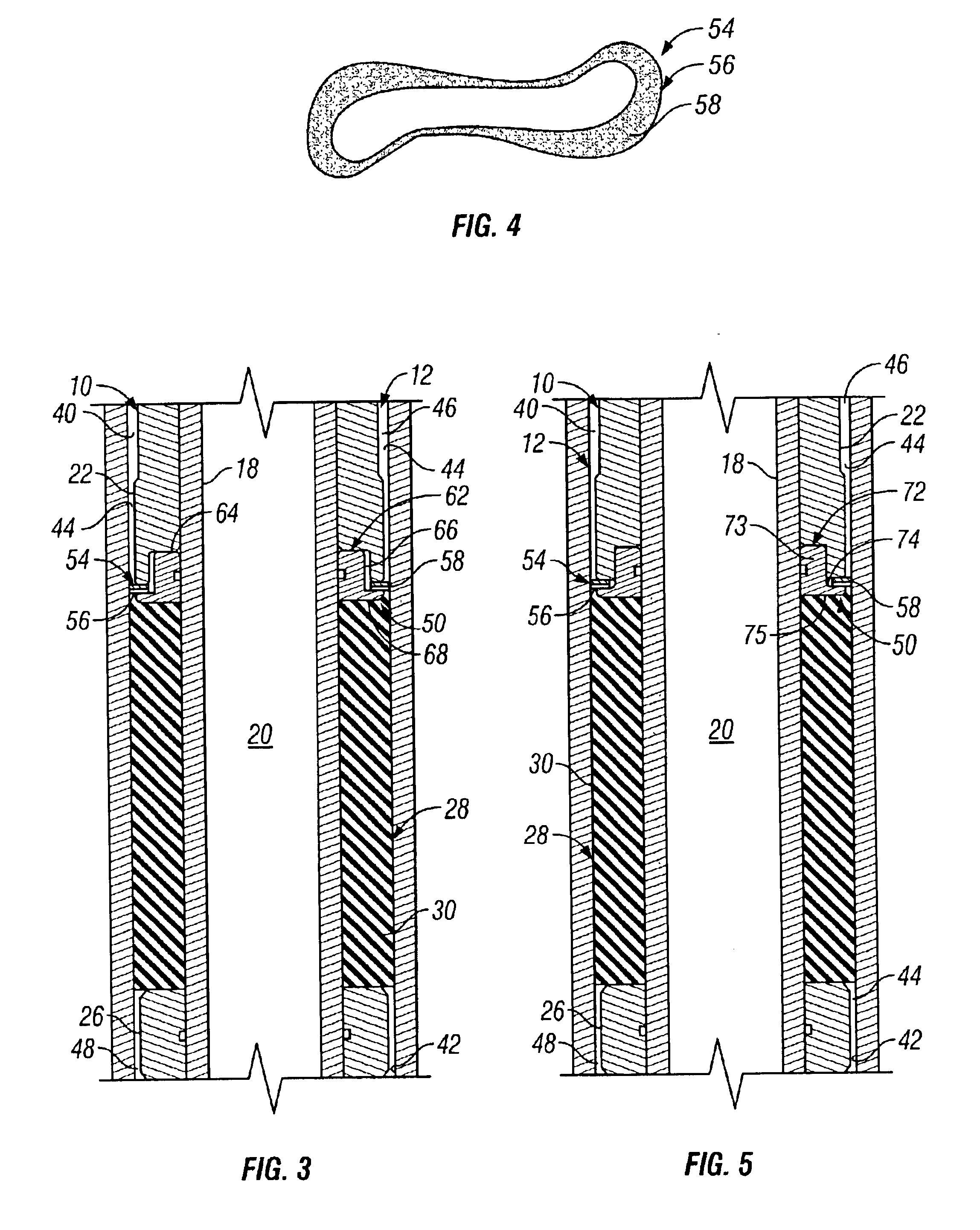
The example expandable member 54 of FIGS. 2 and 3 is a separate component of the anti-extrusion device 50. However, the expandable member 54 may instead be molded into, integral with, or attached to the deformable member 28, or another component. Further, the illustrated expandable member 54 has a continuous, or unbroken, outer surface proximate to the deformable member 28 to prevent extrusion of the deformable member 28 into the expandable member 54 itself. If desired, the expandable member 54 may be contained in, or include, a cover or carrier (not shown), such as a flexible elastomeric, or high-elasticity rubber, sheath. Such configuration may be desirable, for example, to assist in preserving and / or excluding debris from the expandable member 54 during use, providing a continuous outer surface of the expandable member 54, or any combination thereof. However, the continuous outer surface and use of a cover may not be included in some embodiments of the invention.

Referring again t...


PUM


Abstract

An apparatus, system, and method useful for discouraging the extrusion of at least one deformable member of a device into a space adjacent to the deformable member when the device is disposed within a borehole and the deformable member extends from the device to the borehole wall involves at least one expandable member disposed upon the device. The expandable member is expandable into the annulus to reduce the width thereof and retractable therefrom to allow movement of the device within and out of the borehole and redeployment of the expandable member. The apparatus, system, and method are particularly suited for limiting the extrusion of packer elements.

Description

BACKGROUND OF THE INVENTION1. Field of the InventionThe invention relates to methods, apparatus and systems for reducing the size of one or more spaces adjacent to a deformable component of a device. In one embodiment, for example, the invention relates to methods, apparatus and systems for discouraging the extrusion of one or more borehole sealing elements, or members, of a downhole tool into a gap formed between the tool and the borehole. The invention is particularly applicable to packers, including cup and tension set packers.2. Description of Related ArtVarious operations involve the use of devices having one or more deformable members that may undesirably move, or extrude, into a space adjacent to the deformable member. As used throughout this patent, the term “deformable member” means a component, part, or member that may deform under pressure. This often occurs, for example, with devices that are inserted into a borehole, wherein the deformable member is used to form a seal ...

Claims


Application Information

Patent Timeline
Patent Type & Authority Patents(United States)
IPC IPC(8): E21B33/12
CPCE21B33/1216
Inventor MCKEE, L. MICHAELESLINGER, DAVID M.HILL, STEPHEN D.
Owner SCHLUMBERGER TECH CORP
Why Eureka
Try Eureka