Robot hand

a robot and hand technology, applied in the field of robot hands, can solve the problems of requiring a further increase in the degree of freedom, unable to achieve the movement of human hands, and unable to achieve the movement of human hands, and achieve the effect of more complex handling of objects

Inactive Publication Date: 2007-05-22
SHARP KK
View PDF5 Cites 15 Cited by
  • Summary
  • Abstract
  • Description
  • Claims
  • Application Information

AI Technical Summary

Benefits of technology

[0009]Accordingly, the present invention has been devised in light of these problems of the conventional art, and it is an object thereof to provide a technically viable robot hand capable of more complex handling of objects.
[0011]With such a configuration, providing the moving means to a location such that it touches an object, when an object is grasped by the robot hand, makes it possible to move the object by the moving means while grasping the object, thereby enabling more complex handling of the object. Furthermore, as described below, a belt conveyor or the like may be used as the moving means, whereby viability is very high and control of which is easy.
[0019]With this configuration, the object can be moved in a stable manner by each moving means because the moving means touch the object on mutually differing surfaces.

Problems solved by technology

However, while a wide variety of designs have been proposed other than the robot hand disclosed in JP 2001-287182A, the movement of robot hands has thus far failed to achieve that of human hands, which means that there exist many things which can be done with a human hand that cannot be done with a robot hand.
For example, in order to move an object 102 on the palm of a robot hand 101 in the direction of an arrow F while the robot hand 101 holds the object 102 as shown in FIG. 32, the robot hand 101 must be made to perform an extremely complex movement, requiring a further increase in the degree of freedom, making it very difficult to realize such a movement.
Additionally, an appropriate friction surface with the object 102 needs to be provided to the palm, which creates new problems in terms of the shape, material, and so on of the palm, rendering immediate realization impossible.
Further, while a method is conceivable in which a plurality of robot hands is prepared and the object on the palm of the robot hand is moved through the aid of another robot hand, further problems for consideration would arise, such as analysis of locations on the object for the other robot hand to come in contact with, recognition technology, technology for making a plurality of robot hands work in concord, and so on, rendering immediate realization impossible.

Method used


Image

  • Robot hand
  • Robot hand
  • Robot hand

Examples


Embodiment Construction

[0056]Below follows a detailed description of an embodiment of the present invention with reference to the drawings.

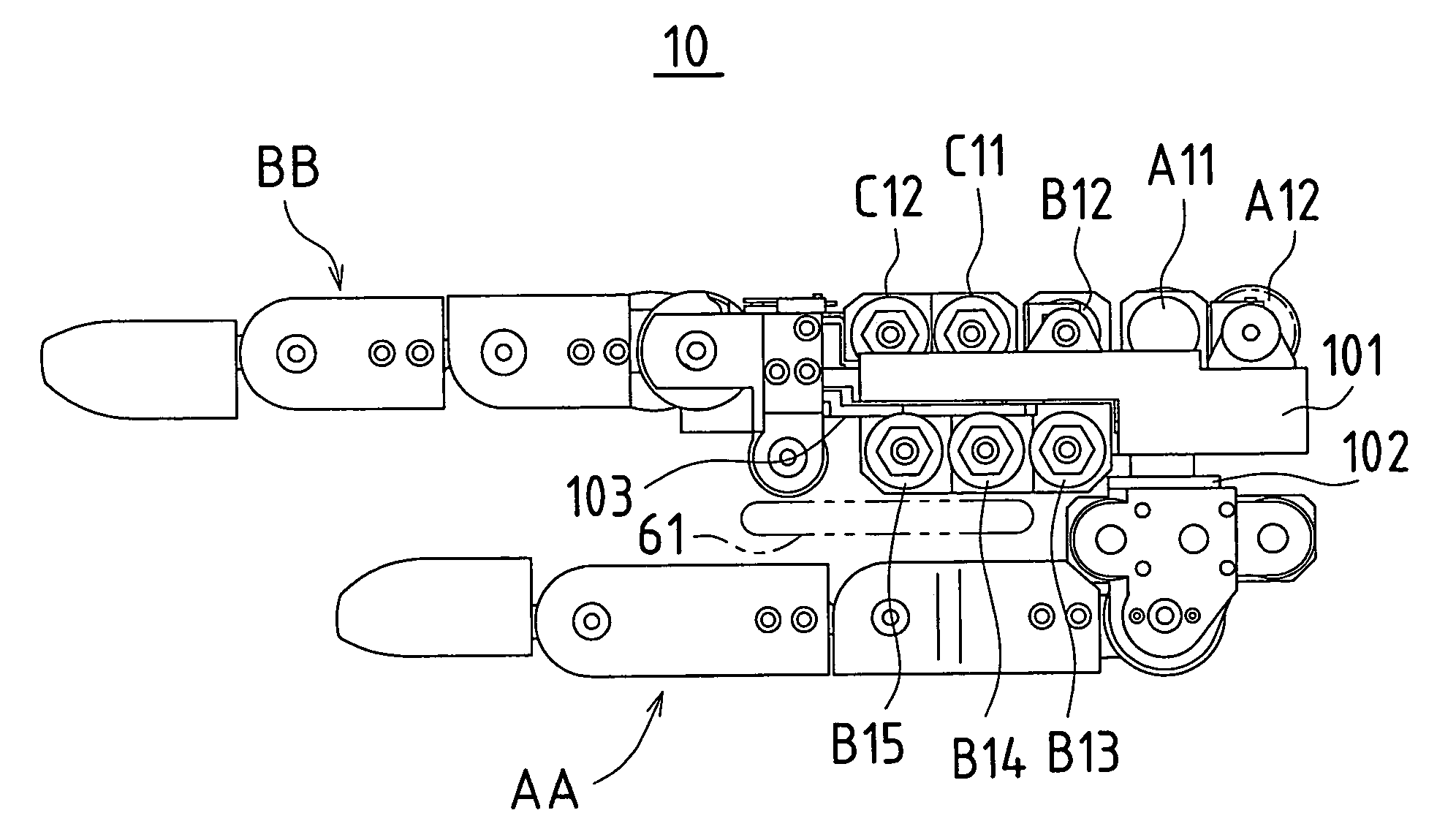
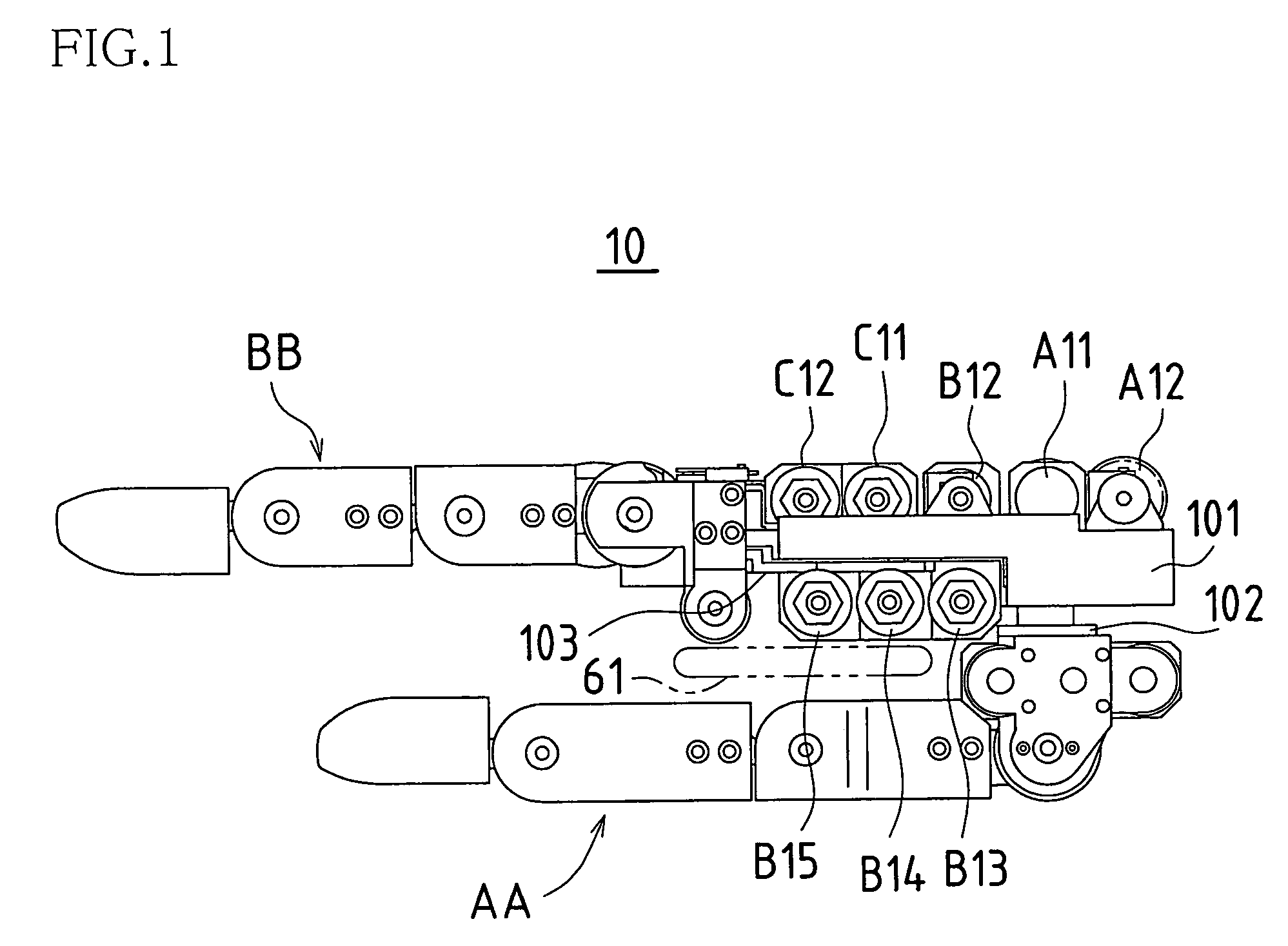
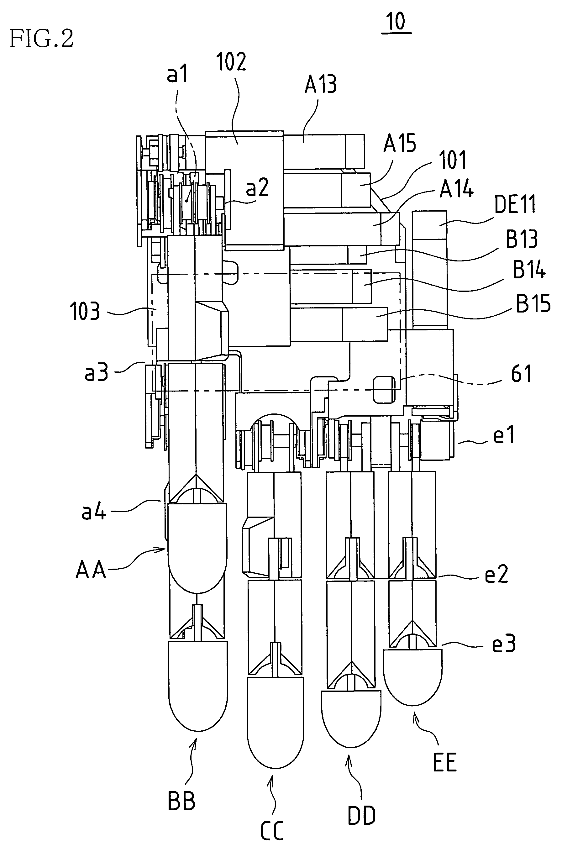
[0057]FIG. 1 is a lateral view showing an embodiment of a robot hand according to the present invention, FIG. 2 is a plan view showing the robot hand according to the present embodiment shown from the palm side, and FIG. 3 is a rear view showing the robot hand according to the present embodiment shown from the back of the hand side.

[0058]In the robot hand 10, a main base 101 corresponds to the palm or the back of the hand, a thumb sub base 102 is pivotally supported on the main base 101 such that it rotates parallel to the palm, and a thumb mechanism AA is supported by the thumb sub base 102. An index finger sub base 103 is pivotally supported on the main base 101 such that it rotates parallel to the palm of the hand, and an index finger mechanism BB is supported on the index finger sub base 103. Further, a middle finger mechanism CC, a ring finger mechanism DD, and a ...


PUM


Abstract

A robot hand has a plurality of fingers and is provided, at a location at which the robot hand touches an object, with a moving means for touching the object and moving the object. The moving means is provided to the palm side of the robot hand and / or the finger pad side of the robot hand.

Description

BACKGROUND OF THE INVENTION[0001]This application claims priority under 35 U.S.C. § 119(a) on Patent Application No. 2004-351481 filed in Japan on Dec. 3, 2004, the entire contents of which are hereby incorporated by reference.[0002]The present invention relates to a robot hand that can perform manual procedures and the like by driving a plurality of fingers.[0003]The device disclosed in, for example, JP 2001-287182A is an example of a conventional device of this type. Here, a drive-source motor is provided to joints of the fingers, a belt bridges an output shaft of the motor and a rotating shaft of the joint, and the rotation of the output shaft of the motor is transmitted to the rotating shaft of the joint via the belt, thereby rotating the joint. These motors and belts are provided to each joint in the finger, rotating each joint and thereby bending and extending the finger.[0004]The degree of freedom of the fingers increases if each joint in the fingers is rotated independently....

Claims


Application Information

Patent Timeline
Patent Type & Authority Patents(United States)
IPC IPC(8): G05B19/10
CPCB25J15/0004B25J15/0009
Inventor TADANO, HIROYUKI
Owner SHARP KK
Why Eureka
Try Eureka