Real-time rendering system and process for interactive viewpoint video

a real-time rendering and viewpoint technology, applied in the field of video rendering, can solve the problems of not being able to achieve the goal of allowing users to interactively change to any desired viewpoint, providing significant further complication, and not being able to achieve the goal of achieving the goal

Inactive Publication Date: 2007-05-22
MICROSOFT TECH LICENSING LLC
View PDF6 Cites 42 Cited by
  • Summary
  • Abstract
  • Description
  • Claims
  • Application Information

AI Technical Summary

Benefits of technology

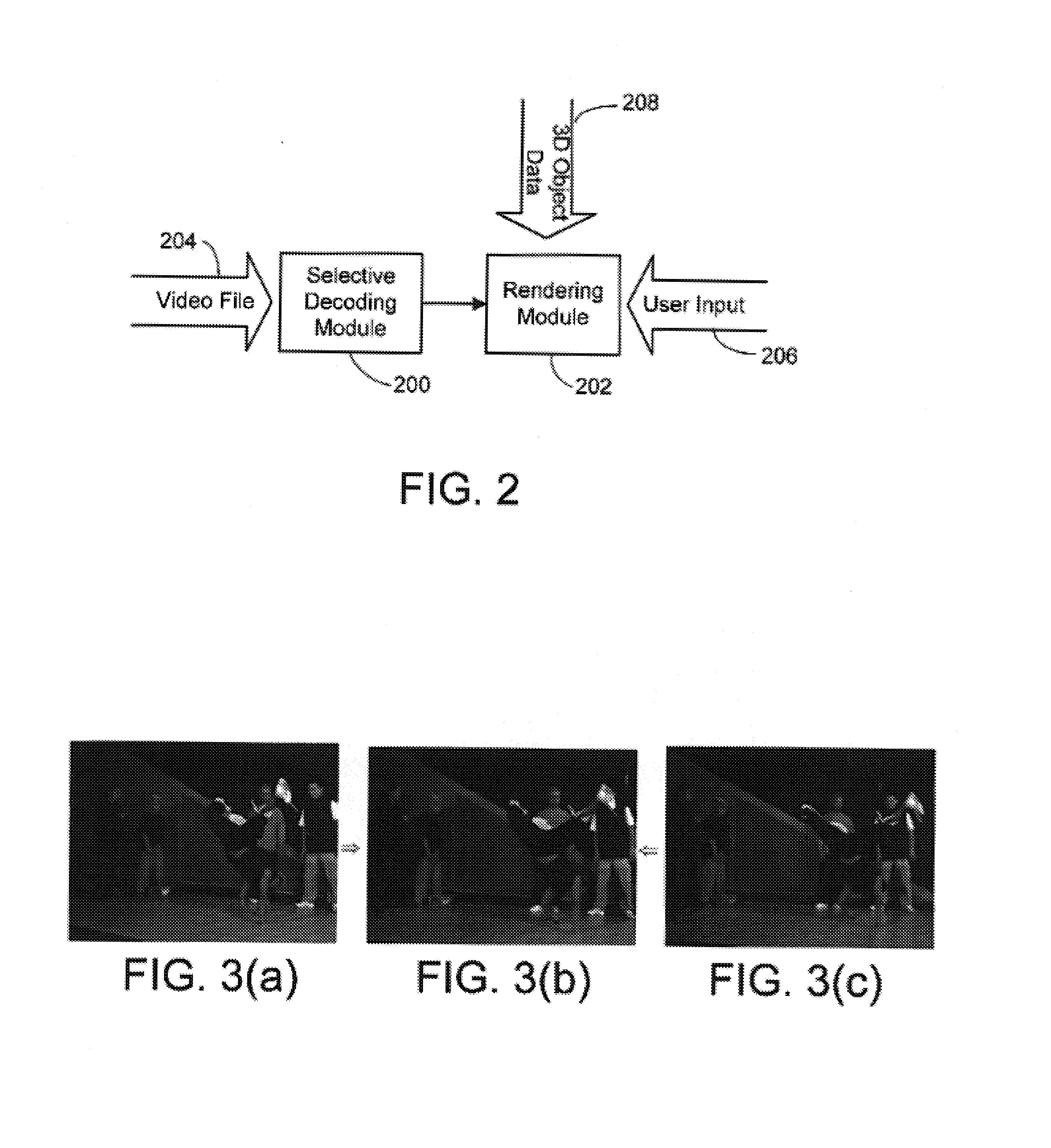
[0020]The rendering and displaying system that is used to play the interactive viewpoint video has a user interface sub-system for inputting user viewpoint selections and displaying rendered interactive viewpoint video frames to the user. To this end, the system includes an input device of some type that is employed by the user to input viewpoint selections on an ongoing basis, and a display device used to display the rendered interactive viewpoint video frames to the user. In addition, the user interface sub-system can include a graphic user interface that allows the user to graphically indicate the viewpoint via the input device.

Problems solved by technology

Unfortunately, this effect is a one-time, pre-planned affair.
Thus, existing systems would not allow a user to interactively change to any desired viewpoint while watching a dynamic image-based scene.
However, extending IBR to dynamic scenes is not trivial because of the difficulty (and cost) of synchronizing so many cameras as well as acquiring and storing the images.
Not only are there significant hurdles to overcome in capturing, representing, and rendering dynamic scenes from multiple points of view, but being able to do this interactively provides a significant further complication.
To date attempts to realize this goal have not been very satisfactory.
Unfortunately, the results look unrealistic because of low resolution, matching errors, and improper handling of object boundaries.
However, it is an expensive system, and provides single viewpoint depth only, which makes it less suitable for multiple view-point video.
However, despite all the advances in stereo and image-based rendering, it is still very difficult to interactively render high-quality, high resolution views of dynamic scenes.

Method used


Image

  • Real-time rendering system and process for interactive viewpoint video
  • Real-time rendering system and process for interactive viewpoint video
  • Real-time rendering system and process for interactive viewpoint video

Examples


Embodiment Construction

[0038]In the following description of the preferred embodiments of the present invention, reference is made to the accompanying drawings which form a part hereof, and in which is shown by way of illustration specific embodiments in which the invention may be practiced. It is understood that other embodiments may be utilized and structural changes may be made without departing from the scope of the present invention.

1.0 Interactive Viewpoint Video

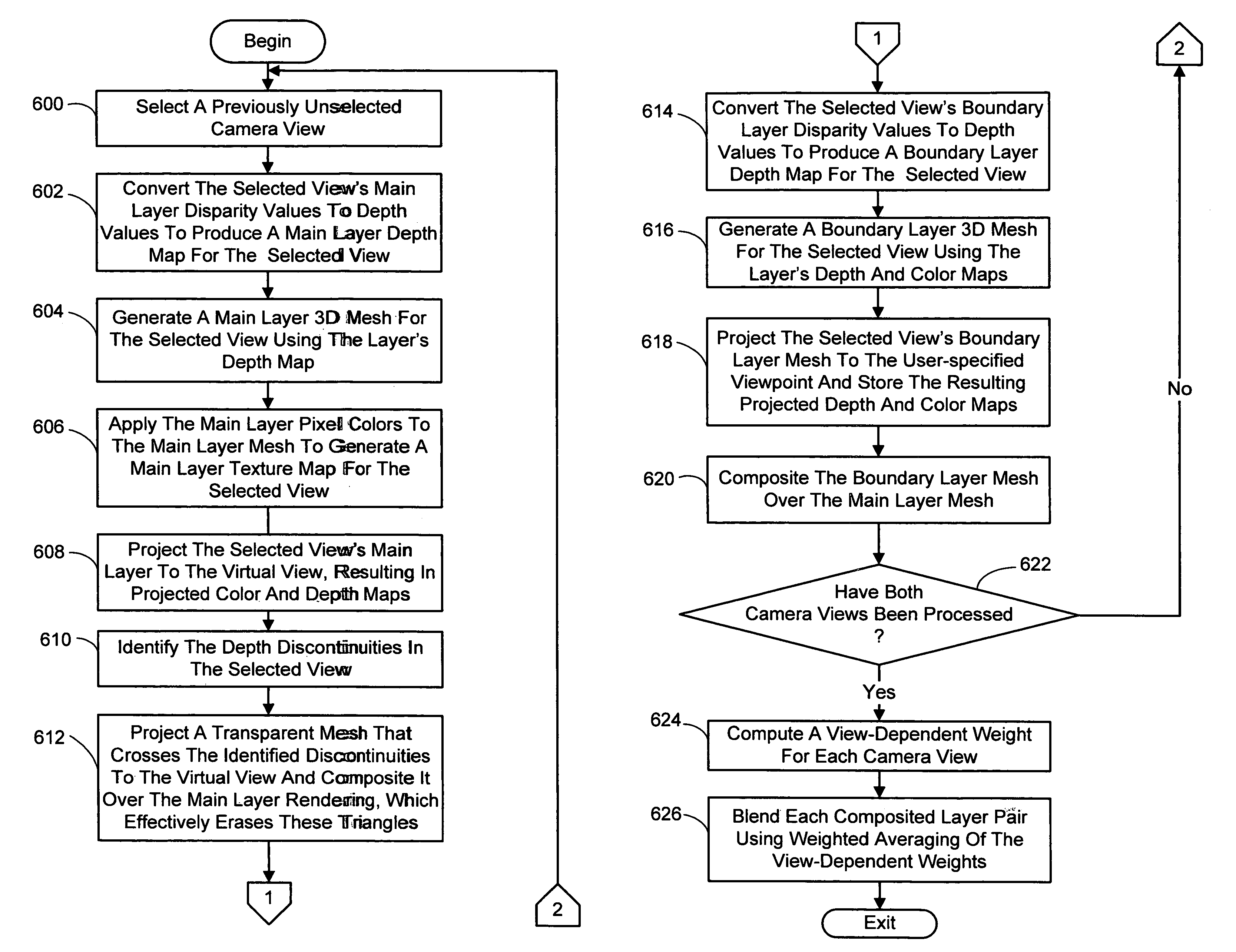
[0039]The present rendering system and process renders and displays dynamic scenes with interactive viewpoint control, in real time, from interactive viewpoint video data. In general, interactive viewpoint video is video in which a user can watch a dynamic scene while manipulating (freezing, slowing down, or reversing) time and changing the viewpoint at will. This video is generated using a relatively small number of cameras to simultaneously capture multiple views of a scene from different viewpoints to produce a set of contemporaneous fram...


PUM


Abstract

A system and process for rendering and displaying an interactive viewpoint video is presented in which a user can watch a dynamic scene while manipulating (freezing, slowing down, or reversing) time and changing the viewpoint at will. The ability to interactively control viewpoint while watching a video is an exciting new application for image-based rendering. Because any intermediate view can be synthesized at any time, with the potential for space-time manipulation, this type of video has been dubbed interactive viewpoint video.

Description

BACKGROUND[0001]1. Technical Field[0002]The invention is related to the rendering of video, and more particularly to a system and process for rendering an interactive viewpoint video in which a user can watch a dynamic scene while changing the viewpoint at will.[0003]2. Background Art[0004]For several years now, viewers of TV commercials and feature films have been seeing the “freeze frame” effect used to create the illusion of stopping time and changing the camera viewpoint. The earliest commercials were produced by using a film-based system, which rapidly jumped between different still cameras arrayed along a rail to give the illusion of moving through a frozen slice of time.[0005]When it first appeared, the effect was fresh and looked spectacular, and soon it was being emulated in many productions, the most famous of which is probably the “bullet time” effects seen in the movie entitled “The Matrix”. Unfortunately, this effect is a one-time, pre-planned affair. The viewpoint traj...

Claims


Application Information

Patent Timeline
Patent Type & Authority Patents(United States)
IPC IPC(8): G06T15/20
CPCG06T15/205
Inventor UYTTENDAELE, MATTHEWWINDER, SIMONZITNICK, III, CHARLESSZELISKI, RICHARDKANG, SING BING
Owner MICROSOFT TECH LICENSING LLC
Why Eureka
Try Eureka