Device and method for reducing glass flow during the manufacture of microchannel plates

a microchannel plate and glass flow technology, applied in the field of microchannel plates, can solve problems such as rupture, reduced structural integrity, and missing channel walls

Inactive Publication Date: 2007-05-22
HARRIS CORP
View PDF15 Cites 11 Cited by
  • Summary
  • Abstract
  • Description
  • Claims
  • Application Information

AI Technical Summary

Problems solved by technology

Movement of the fibers closer together can lead to missing channel walls after the etch process because there will not be enough cladding glass to form a wall between the channels.
These missing channel walls can lead to any number of defects such as ion barrier or film emission points, reduced structural integrity and ruptures.

Method used


Image

  • Device and method for reducing glass flow during the manufacture of microchannel plates
  • Device and method for reducing glass flow during the manufacture of microchannel plates
  • Device and method for reducing glass flow during the manufacture of microchannel plates

Examples


Embodiment Construction

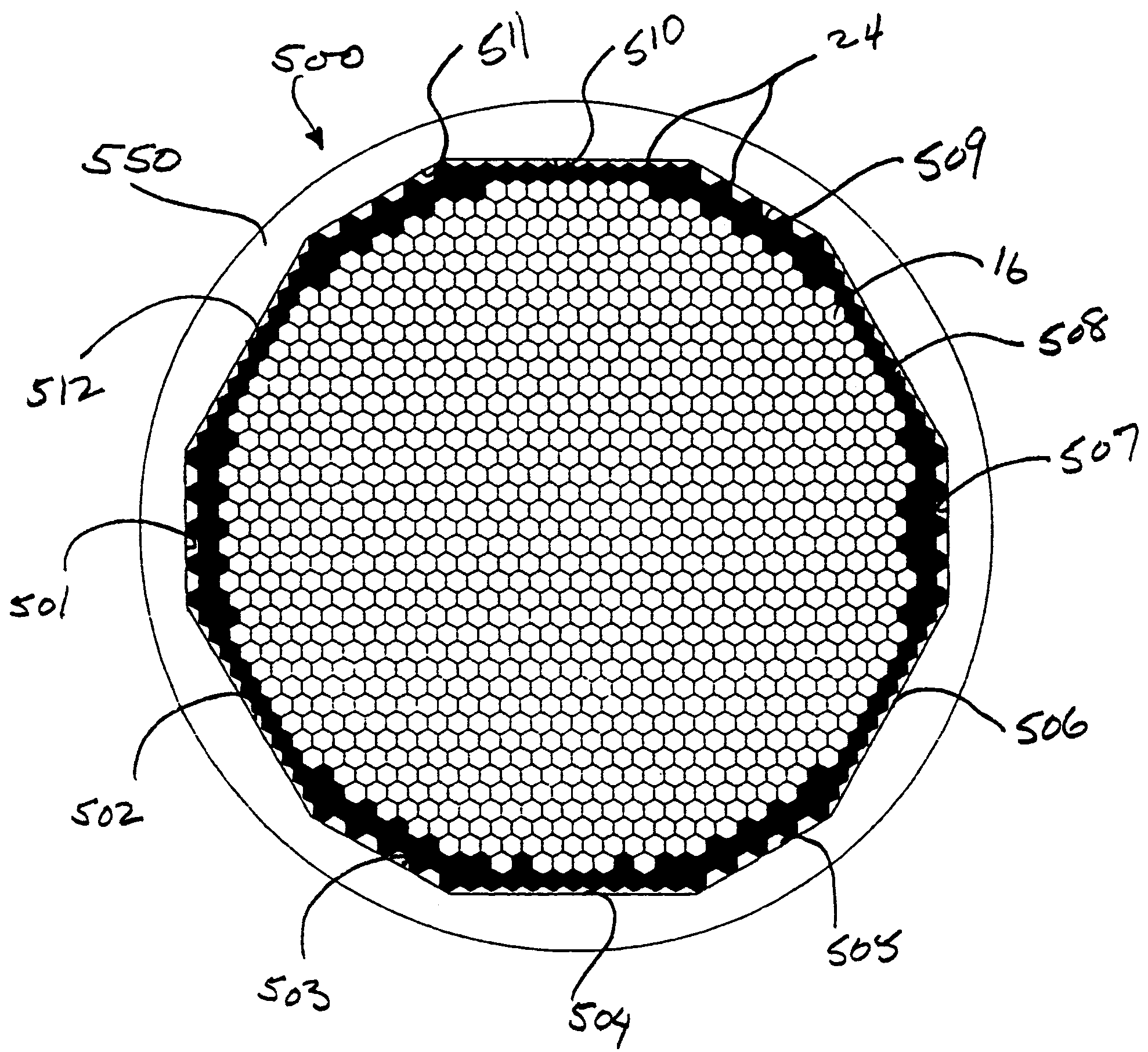
[0014]The present invention relates to a glass packing tube 550 used to form boules and which tube is configured to reduce the amount of glass flow when fusing the boule during manufacture of microchannel plates. More specifically, the packing tube 550 according to the present invention is made of non-etchable glass and has multiple flat interior surfaces 501 through 512. These flat surfaces are planar surfaces and allow the packing of fiber bundles 16 and support rods 24 within the glass packing tube 550 while maintaining minimal open space (as compared to a round internal surface) between the outermost support rods and the interior surface of the packing tube. This minimization of open space is advantageous because it reduces the flow of glass during the fusion process that forms a fused boule.

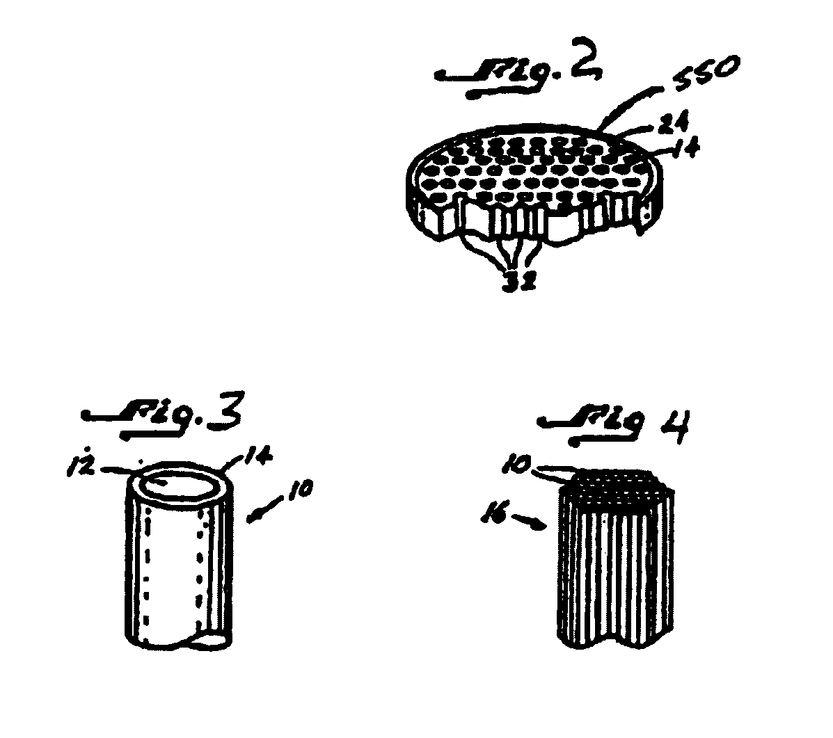
[0015]FIG. 3 shows a starting fiber 10 used to manufacture a microchannel plate for use as an electron multiplier. The fiber 10 includes a glass core 12 and a glass cladding 14 surrounding t...


PUM

PropertyMeasurementUnit
widthaaaaaaaaaa
dimensionaaaaaaaaaa
shapeaaaaaaaaaa

Abstract

The present invention provides a glass packing tube for use in fabricating a microchannel plate. The glass tube has a plurality of flat inner surfaces and is used to form a boule including a plurality of optical fibers located in the tube and a plurality of support rods between the first optical fibers and the flat surfaces whereby the tube, fibers and rods are fused together with reduced glass flow.

Description

FIELD OF THE INVENTION[0001]The present invention relates to microchannel plates for use with image intensifiers, and more specifically, to an arrangement for reducing glass flow during the manufacture of the plates.BACKGROUND OF THE INVENTION[0002]Microchannel plates are used as electron multipliers in image intensifiers. They are thin glass plates having an array of channels extending therethough and are located between a photocathode and a phosphor screen. An incoming electron from the photocathode enters the input side of the microchannel plate and strikes a channel wall. When voltage is applied across the microchannel plate these incoming or primary electrons are amplified, generating secondary electrons. The secondary electrons then exit the channel at the back end of the microchannel plate and are used to generate an image on the phosphor screen.[0003]In general, fabrication of a microchannel plate starts with a fiber draw processes. An etchable core rod is drawn within a non...

Claims


Application Information

Patent Timeline
Patent Type & Authority Patents(United States)
IPC IPC(8): G02B6/04C03B37/012H01J43/24
CPCC03B37/01214H01J43/246C03B2203/40
Inventor MABRY, THOMAS T.
Owner HARRIS CORP
Why Eureka
Try Eureka