
Operator guiding system

a guiding system and operator technology, applied in the field of operator guiding system, can solve the problems of operator falling, difficulty in operation, and longer moving distance and time, and achieve the effect of facilitating the operation of positioning operation, pile-driving operation, or the like by the operator

Inactive Publication Date: 2007-05-22
KK TOPCON
View PDF28 Cites 81 Cited by
  • Summary
  • Abstract
  • Description
  • Claims
  • Application Information

AI Technical Summary

Benefits of technology

[0009]The object of the present invention is to provide an operator guiding system that makes the positioning operation, the pile-driving operation, or the like by the operator easier.

Problems solved by technology

The operator, when moving to the straight line connecting the base station and the target point, needs to make sure whether or not he / she has reached the straight line by constantly looking into the display of the display means of the mobile station and the collimation direction by the base station, which has been complicate as an operation, and the operator has been in danger of falling when moving on unleveled ground before construction.
Furthermore, since the operator needs to move on a route passing {circle around (1)}, {circle around (2)} and {circle around (3)} until he / she reaches the target point, both moving distance and time have taken longer, and it has been very operation-inefficient.
When the collimation direction of the base station is needed to confirm visually, there have been cases where such an operation was difficult due to a visual power of the operator.

Method used


Image

  • Operator guiding system
  • Operator guiding system
  • Operator guiding system

Examples


Embodiment Construction

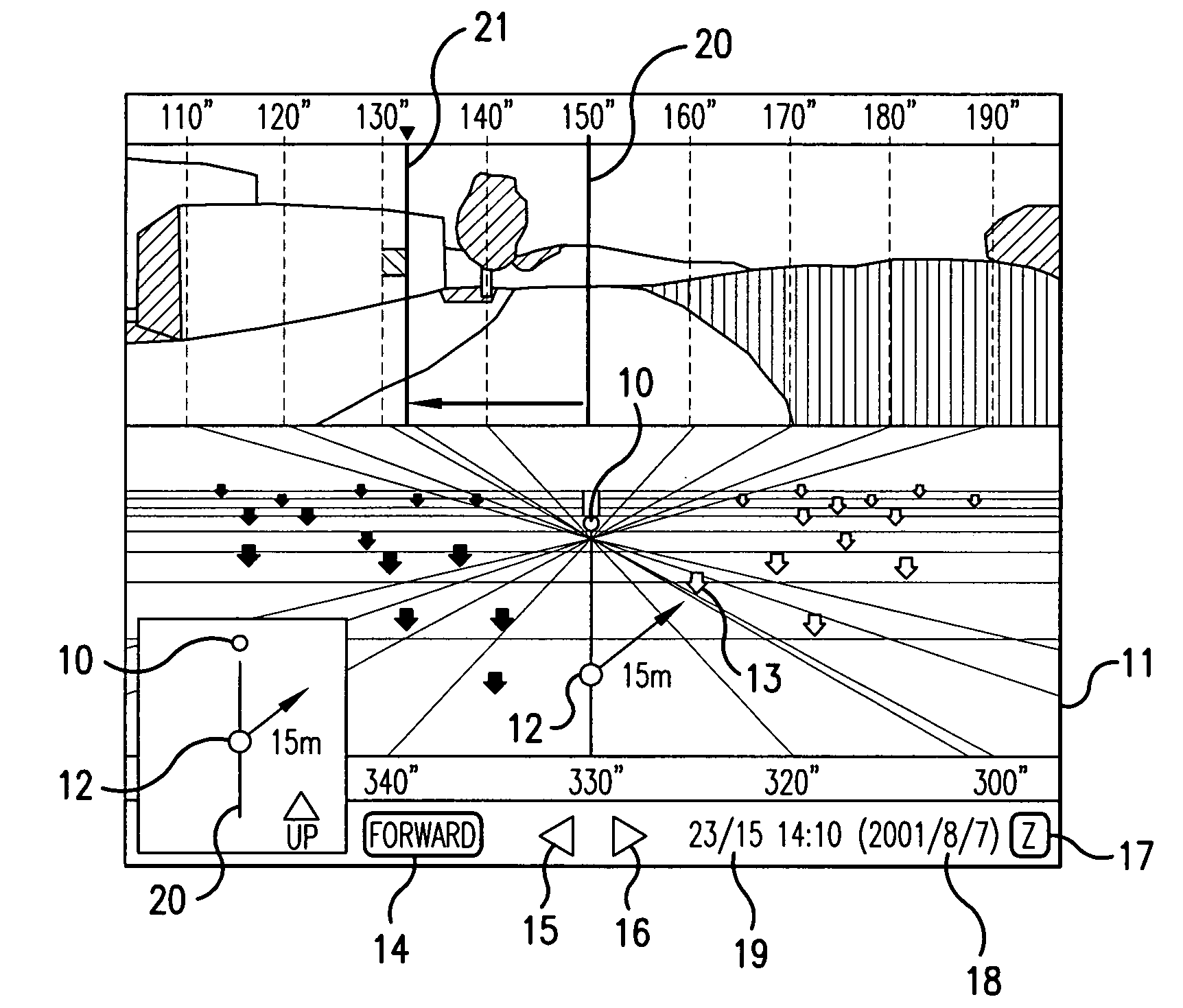
[0115]FIG. 1 shows an example of the display mode of the display means of a mobile station 12.

[0116]Particularly, FIG. 1 shows an example of the Forward (foreground) mode display, in which the image of the landscape when the operator sees in the direction of a base station 10 from the mobile station 12 that he / she possesses to move and the image of the artificial landscape are simultaneously displayed. The image of the artificial landscape is displayed in a small rectangle at the lower left corner of a display screen 11.

[0117]In FIG. 1, the next target points positions in a middle region between the current position of the operator (mobile station 12) and the base station 10.

[0118]A plurality of target points are shown by downward arrows. There exist 3 kinds of arrows showing the target points, where an outline arrow denotes an unprocessed target point, a bold outline arrow denotes a target point to be processed next, and a black arrow denotes a processed target point. The target po...


PUM


Abstract

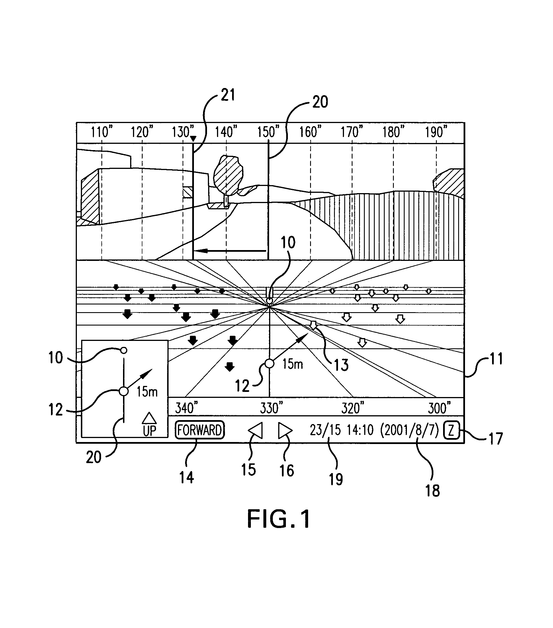
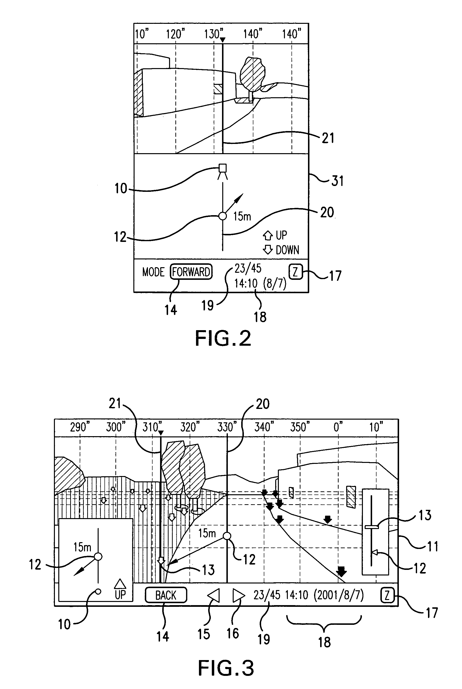
A base station is installed in a predetermined area where a large number of target points are studded around the station. When the operator moves a mobile station around the base station, display means is provided for both or either of the base station that guides the operator and the mobile station, and a display screen of the display means displays 2 kinds of a Forward (foreground) mode and a Back (background) mode. In the Forward (foreground) mode, the display screen of the display means displays a landscape in a forward direction (opposite direction to the mobile station by 180° when seen from the base station) of the operator (mobile station) when the operator sees the base station from the current position of the mobile station, or from the next target point if the operator reaches the next target point. In the Back (backward) mode, the display screen of the display means displays the landscape in a backward direction (direction of the operator and the mobile station when seen from the base station) of the operator (mobile station) when the operator sees the base station from the current position of the mobile station, or from the next target point if the operator reaches the next target point. The relationship between the mobile station and the next target point is displayed on an imaginary landscape in an imaginary manner so that the operator can see the direction and distance for movement.

Description

BACKGROUND OF THE INVENTION[0001]1. Technical Field of the Invention[0002]The present invention relates to an operator guiding system in a pile-driving operation, a positioning operation, or the like.[0003]2. Related Art[0004]FIG. 7 shows a schematic view of a conventional operator guiding system in the pile-driving operation or the positioning operation.[0005]Firstly, a base station 71 is arranged at a good position for overlooking the entire operation site such that a large number of target points (target points where pile-driving or positioning should be performed) are studded around the base station 71 (regularly composed of an instrument main body supported by a tripod) that measures positional coordinates. When the relation among the base station 71, a mobile station 72 that an operator possesses to carry, and particularly the next target point 73 among a large number of the target points for the pile-driving, the positioning operation, or the like, is as shown in FIG. 7, the ...

Claims


Application Information

Patent Timeline
Patent Type & Authority Patents(United States)
IPC IPC(8): G01V3/38G01C15/00G09B29/00G06Q50/00G06Q50/08G09B29/10
CPCG01C15/00
Inventor OOTOMO, FUMIOKIMURA, AKIOKUMAGAI, KAORUOSARAGI, KAZUKIHAYASHI, KUNIHIRO
Owner KK TOPCON
Learn More