Incremental locking hinge assembly

a hinge assembly and hinge technology, applied in the field of hinge assembly, can solve the problems of statically mounted one-size-fits-all display, difficult if not impossible for some users to view, interact with, and monitor properly, and achieve the effect of increasing the configurability of the support assembly

Inactive Publication Date: 2007-05-29
TOSHIBA INT
View PDF23 Cites 10 Cited by
  • Summary
  • Abstract
  • Description
  • Claims
  • Application Information

AI Technical Summary

Benefits of technology

[0006]In an aspect, the present invention relates to a hinge system that provides significant adjustability to accommodate the variance in sizes of a main body to which the apparatus may be affixed, a cantilever member to which the apparatus is affixed so as to allow rotation or translation with respect to the main body. The hinge assembly may be used for affixing a wide variety of objects together so as to allow movement of a cantilever member relative to a main body.
[0007]The hinge system can be used to support a cantilever member in a static position and additionally allows movement and adjustment to the position of the cantilever member relative to the main member and / or a user. The cantilever member may include, for example, a display, a control panel, an information panel, a sensor, or a speaker. Thus, increased configurability of support assemblies is provide to allow users of varying physical attributes and users in varying positions to interact with, utilize or view the object supported by the assembly.

Problems solved by technology

These previous assemblies offer few, if any positioning options.
Since users of a UPS, and the UPS itself, can vary significantly in height and size, a staticly mounted one-size-fits-all display would be difficult if not impossible for some users to view, to interact with, and to properly monitor.

Method used


Image

  • Incremental locking hinge assembly
  • Incremental locking hinge assembly
  • Incremental locking hinge assembly

Examples


Embodiment Construction

Illustrative Operating Environment

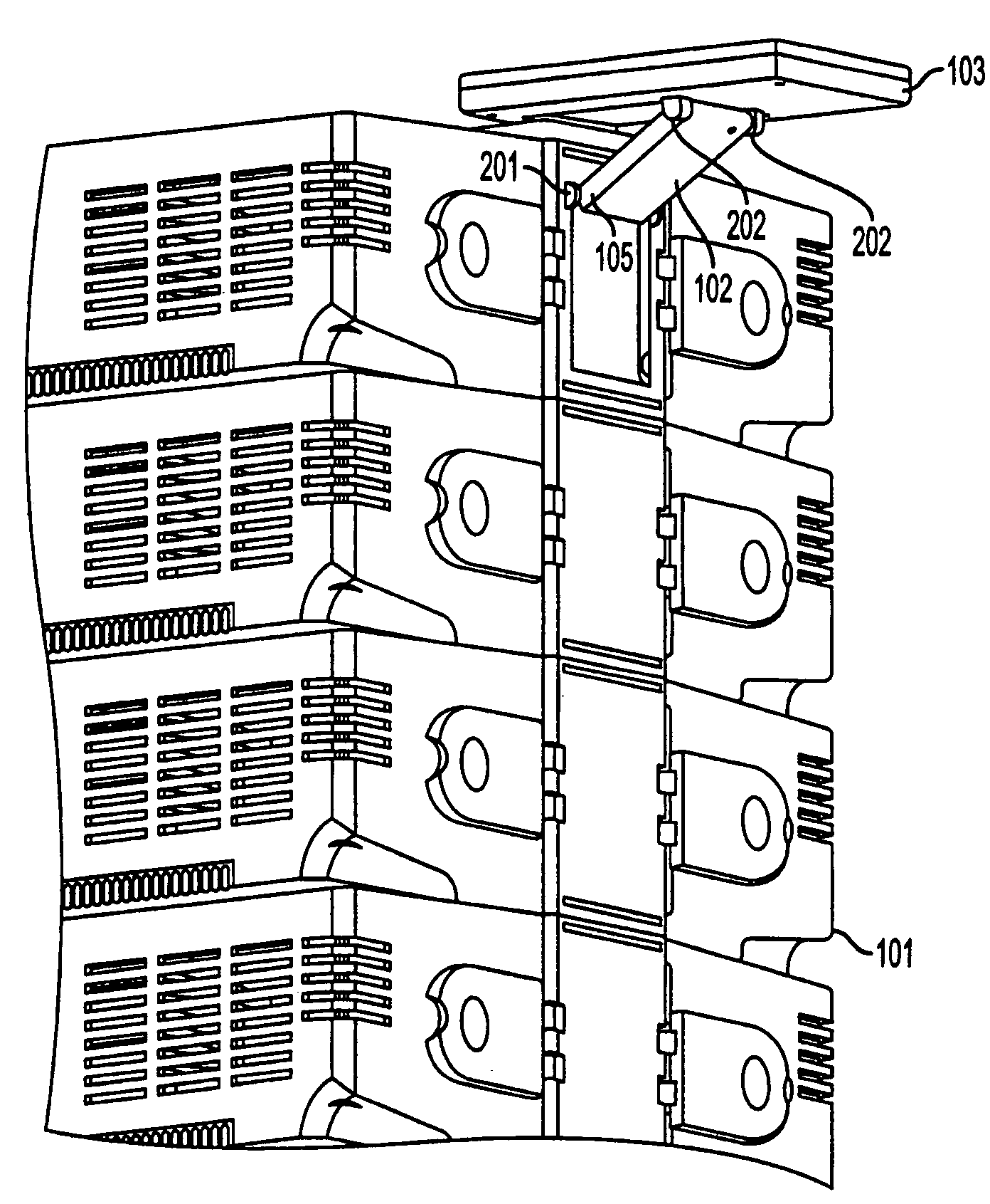
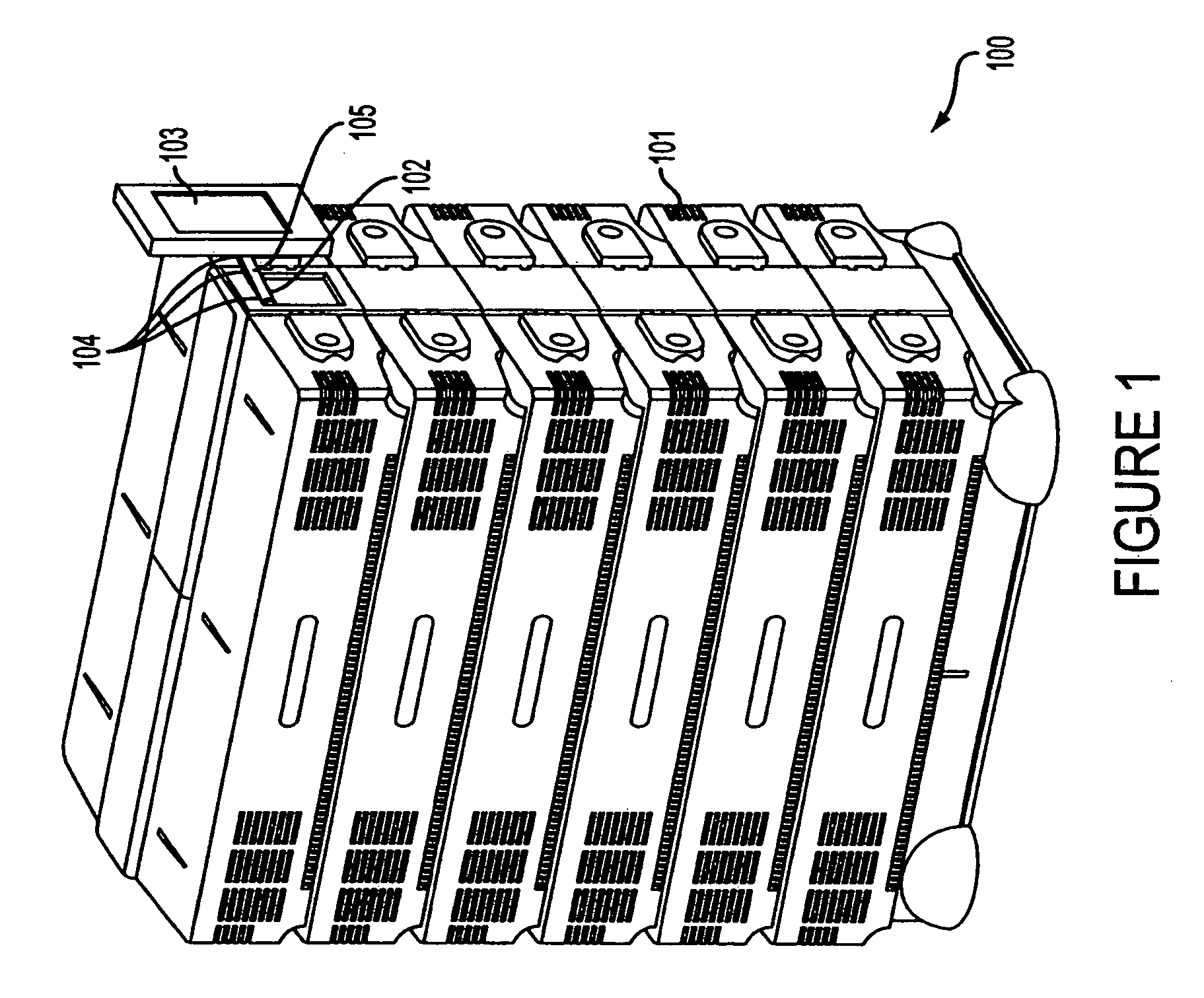
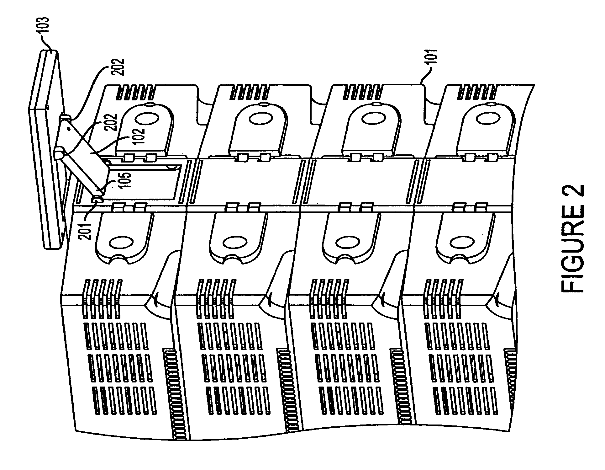
[0026]FIGS. 1–4 depict an uninterrupted power supply system 100 utilizing an inventive hinge assembly 201, 202 (see FIGS. 2–3) which supports a cantilevered object, such as a display unit. System 100 includes a UPS 101, a support member 102, and a display 103 that is linked to the UPS through the support member and several hinge points 104 to allow numerous view angles or control positions of the UPS 101. It should be recognized that the display 103 is electronically coupled to the hardware and may be used to control operation of the UPS.

[0027]Significant adjustability of the location and orientation of the display 103 linked to the UPS is provided in aspects of the present invention. A hinge assembly is utilized to allow for both support as well as the desired variability of the display 103 on the UPS 101. Serving as a connection between the UPS 101, the support member 102, and the display 103, hinge points 104 allow rotational movement of the supp...


PUM


Abstract

A hinge assembly containing a receiver member having a corrugated inner surface and a locking pin for being pivotally disposed within the receiver portion about an axis. The locking pin and receiver member have complementary corrugated engaging surfaces that allow the hinge to provide support for a cantilevered structure when the pin and receiver are engaged. When the complimentary pin and receiver are disengaged, the pin member can be incrementally rotated so as to allow the cantilevered structure to be positioned in a different position or orientation.

Description

FIELD OF THE INVENTION[0001]Present invention is directed generally to a hinge assembly. More particularly, aspects of the present invention relate to an incremental locking hinge assembly for supporting objects.BACKGROUND OF THE INVENTION[0002]Individuals in computer rooms and other environments operate and use equipment which may need multiple positions for various uses. Displays and similar objects can be hung from a computer. For example, in a computer room environment previous assemblies for supporting cantilevered objects have been static. These previous assemblies offer few, if any positioning options.[0003]A need exists for a support mechanism in use with the display of an Uninterruptible Powers Source, hereafter “UPS”. Since users of a UPS, and the UPS itself, can vary significantly in height and size, a staticly mounted one-size-fits-all display would be difficult if not impossible for some users to view, to interact with, and to properly monitor.[0004]Thus, there is a nee...

Claims


Application Information

Patent Timeline
Patent Type & Authority Patents(United States)
IPC IPC(8): E05D11/10G06F1/16
CPCG06F1/1601E05D11/1078E05Y2900/606Y10T16/54028Y10T16/54038Y10T16/540255
Inventor VACKAR, MARK A.
Owner TOSHIBA INT
Why Eureka
Try Eureka