Method and device for controlling a drive unit

a technology of drive unit and drive unit, which is applied in the direction of electric control, idling device, charge feed system, etc., can solve the problems of at least partly ineffective compensation for and external interventions are unable to reduce the engine's total torque to below the modeled consumer torqu

Inactive Publication Date: 2007-05-29
ROBERT BOSCH GMBH
View PDF6 Cites 2 Cited by
  • Summary
  • Abstract
  • Description
  • Claims
  • Application Information

AI Technical Summary

Benefits of technology

[0002]The method according to the present invention and the device according to the present invention for controlling a drive unit have the advantage that the ratio of a first priority request for modification of the predefined setpoint value as a function of the at least one load to be compensated to a second priority request for modification of the predefined setpoint value as a function of the at least one reducing request may be varied for different drive unit operating states. This means that, based on the operating state of the drive unit, it is possible to prioritize the inclusion in the calculation of the at least one reducing request for determining the predefined setpoint value or the inclusion in the calculation of the at least one load to be compensated for determining the predefined setpoint value. Thus in drive unit operating states requiring load compensation, e.g., to avoid stalling of the drive unit, modification of the predefined setpoint value may be prioritized as a function of the at least one load to be compensated for. In drive unit operating states in which compensating for load presents no difficulties, e.g., if the engine speed is well above idle speed, modification of the predefined setpoint value may be prioritized as a function of the at least one reducing request.
[0004]It is particularly advantageous if the different operating states are defined by a variable measure of the activity level of a drive unit idle-speed controller. This means the drive unit's various operating states may be unambiguously assigned to different levels of need for load compensation, and the ratio of the first priority request to the second priority request may be determined in a particularly simple manner.
[0009]As the need for load compensation increases, in particular as the engine speed approaches idle speed, and therefore as the ratio of the first priority request to the second priority request increases, in a particularly simple manner, the weighting for modification of the predefined setpoint value as a function of the at least one load to be compensated for after the minimum selection may be increased relative to the weighting for modification of the predefined setpoint value as a function of the at least one load to be compensated for prior to the minimum selection. This ensures that, as load compensation becomes increasingly necessary, it is increasingly included in the calculation of the setpoint value for drive unit output after the minimum selection and is thus decreasingly affected by the at least one reducing request.

Problems solved by technology

This renders the compensation for the modeled consumer torque at least partly ineffective.
If the point at which the modeled consumer torque is included in the calculation of the setpoint value is after the reducing external interventions, the reducing external interventions are unable to reduce the engine's total torque to below the modeled consumer torque.

Method used


Image

  • Method and device for controlling a drive unit
  • Method and device for controlling a drive unit
  • Method and device for controlling a drive unit

Examples


Embodiment Construction

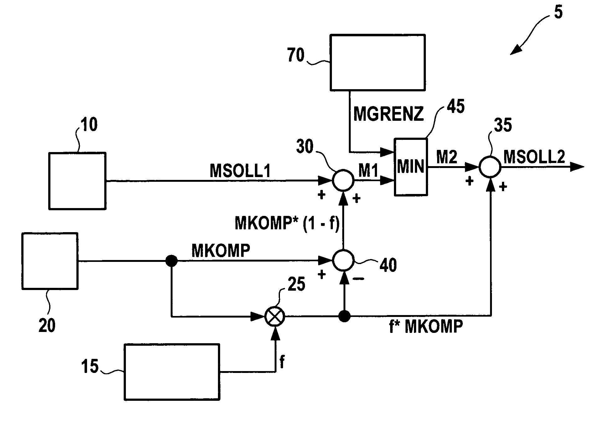
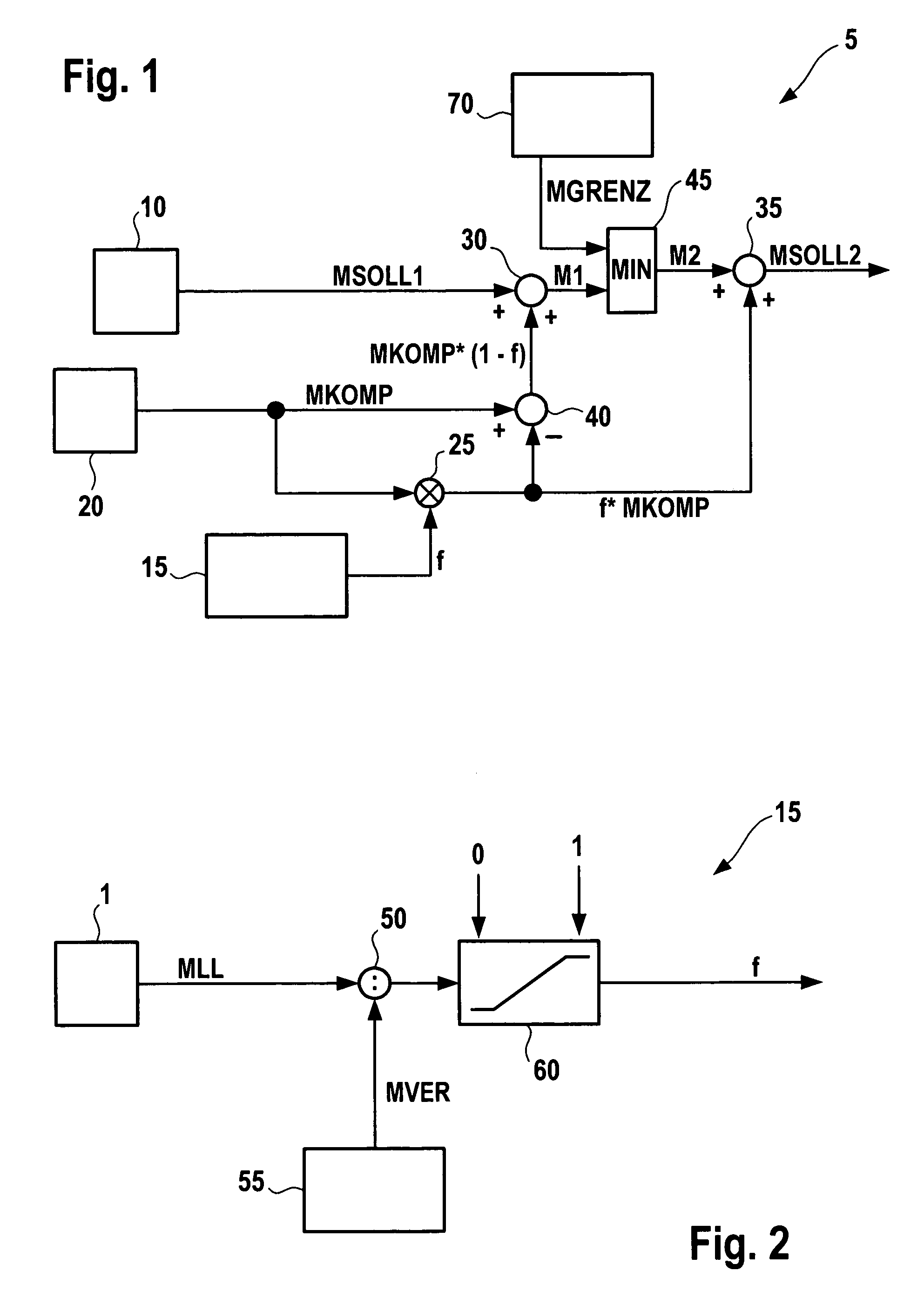
[0014]In FIG. 1, reference numeral 5 indicates a device for controlling a drive unit which drives a motor vehicle, for example. Device 5 may be for example an engine controller for the vehicle. FIG. 1 only shows the components of engine controller 5 which are necessary for the functioning of the present invention. Engine controller 5 determines a setpoint value for an output variable of the drive unit. The output variable may be for example a torque or power or a variable derived from the torque and / or power. Below, it is assumed by way of example that the output variable is a torque. Engine controller 5 includes predefinition unit 10 which, in a manner known to those skilled in the art, determines drive unit torque first setpoint value MSOLL1. Predefinition unit 10 may determine drive unit torque first setpoint value MSOLL1 as a function of the driver's intent; this may be determined from the degree of actuation of the vehicle's accelerator pedal. First setpoint value MSOLL1 is sen...


PUM


Abstract

A method and a device for controlling a drive unit which allow an improved transition between idle regulation and drive unit propulsion are provided. A setpoint value for an output variable of the drive unit is predefined, it being possible to modify the setpoint value as a function of at least one reducing request and as a function of at least one load to be compensated for. The ratio of a first priority request for the modification of the predefined setpoint value as a function of the at least one load to be compensated for to a second priority request for the modification of the predefined setpoint value as a function of the at least one reducing request may be varied for different drive unit operating states.

Description

BACKGROUND INFORMATION[0001]Methods are known for controlling a drive unit in which a setpoint value for a drive unit output variable is predefined, it being possible to modify the predefined setpoint value as a function of at least one reducing request and at least one load to be compensated for. For example in the case of propulsion of a motor vehicle by the drive train, it is known that a modeled consumer torque of loads for which compensation is required, e.g., secondary equipment, may be included in calculations at a specified point in the path for determining the setpoint torque of an engine controller. If that point of inclusion in the calculation is before a minimum selection having reducing external interventions, e.g., from a transmission controller or an electronic stability program, limits must be applied to these external interventions if the vehicle's engine is close to idle speed, because the idle-speed controller generally relies on support via the compensation for t...

Claims


Application Information

Patent Timeline
Patent Type & Authority Patents(United States)
IPC IPC(8): F02D45/00F02D41/16
CPCF02D41/083F02D41/1497F02D2250/18F02D2250/21
Inventor ANZ, RUPRECHT
Owner ROBERT BOSCH GMBH
Why Eureka
Try Eureka