Steering system
- Summary
- Abstract
- Description
- Claims
- Application Information
AI Technical Summary
Benefits of technology
Problems solved by technology
Method used
Image
Examples
second embodiment
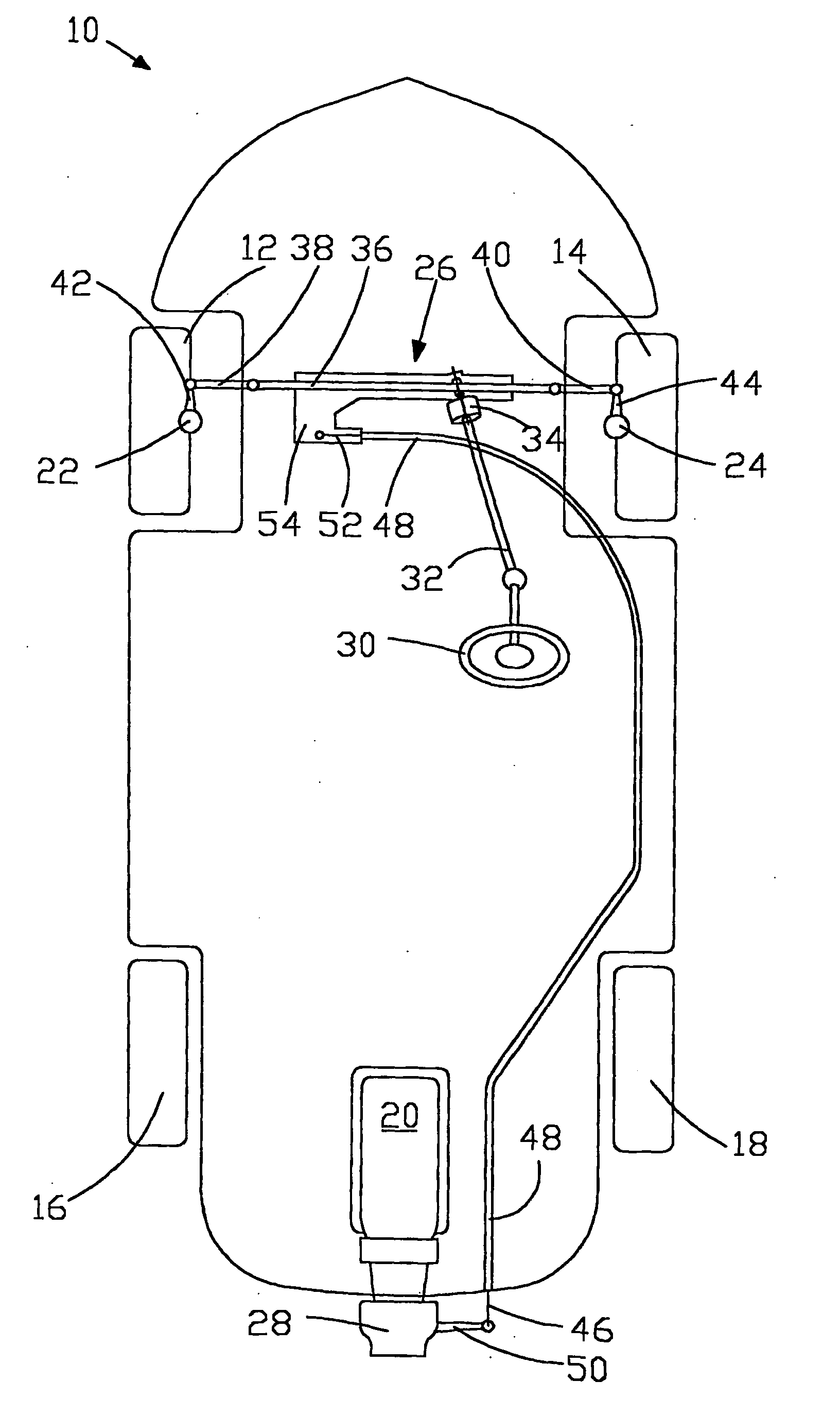
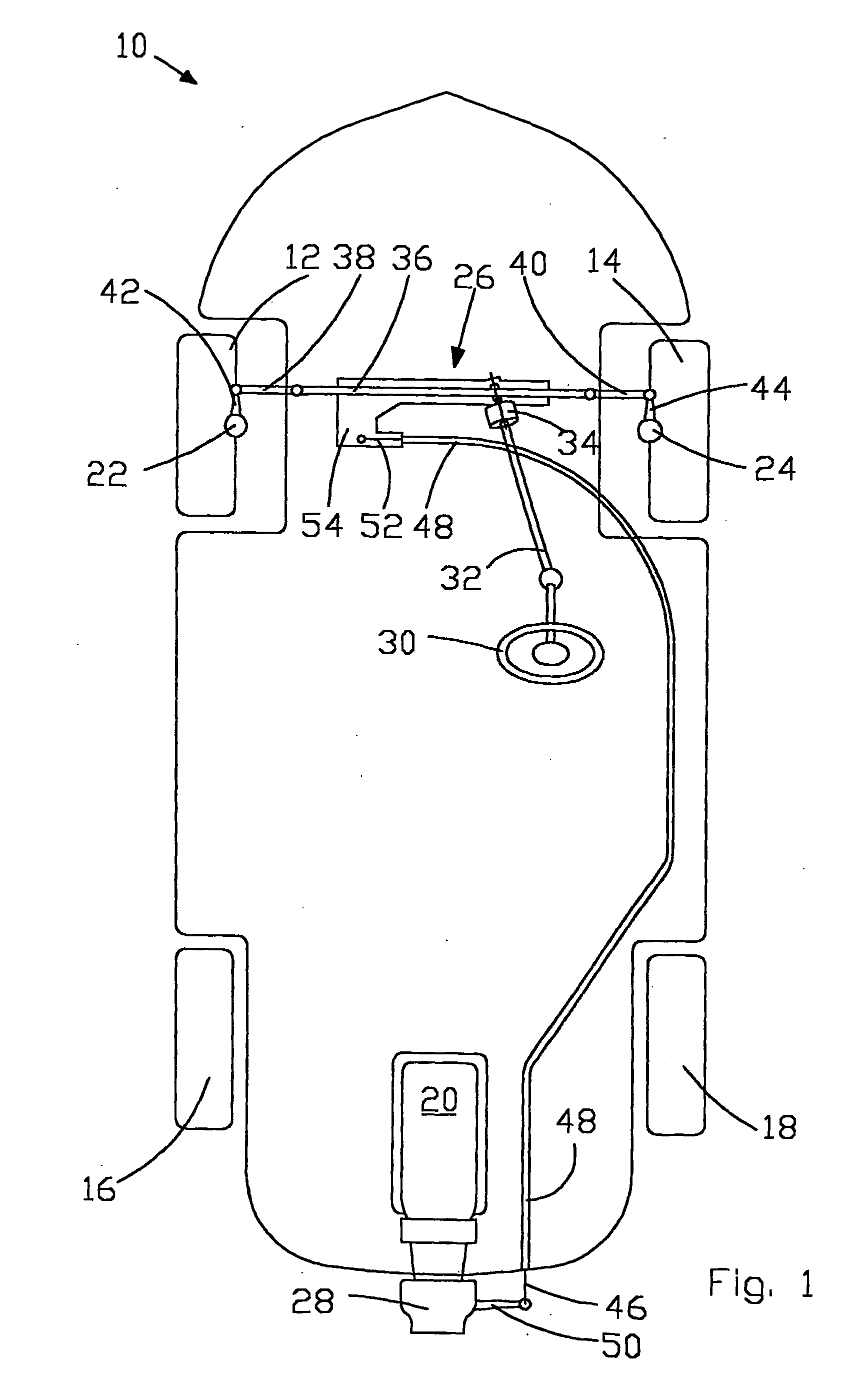
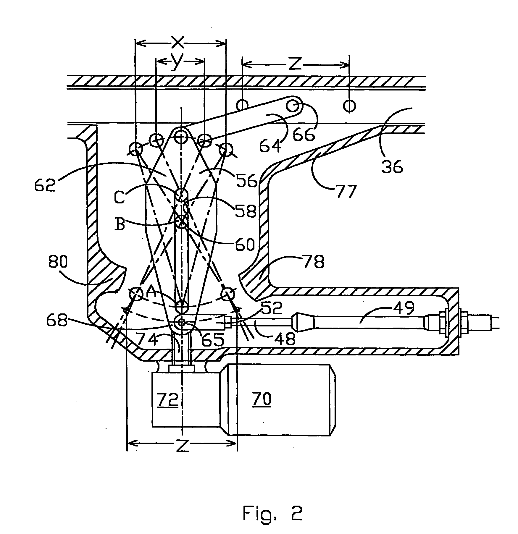
[0039]FIGS. 3 and 4 show a steering system in accordance with the invention. The steering system of FIGS. 3 and 4 is very similar to that of FIGS. 1 and 2 and operates in the same way, the only differences being that:
[0040] the link 64 is attached to a drive lug 90 projecting from the steering rack 36; and movement of the first end 62 of the lever 56 is guided by engagement of a pivot pin 92, which connects the link 64 to the first end 62 of the lever, with a guide track 94 formed in the housing 77 of mechanism 54.
[0041] The guide track 94 is formed in an upper portion 96 of the housing 77 and receives an end of the pivot pin 92. The guide track 94 is shaped to conform with the locus of the pivot pin 92 as the first end 62 of the lever pivots about the fulcrum pin 60, as can best be seen in FIG. 3. This arrangement helps to ensure proper movement of the lever 56 and improves the overall stability of the mechanism.
[0042]FIG. 4 also shows the adjust mechanism for the fulcrum pin 60 ...
third embodiment
[0043] the invention is shown in FIGS. 5 to 7. In this embodiment, the steering rack assembly 26 is power assisted and movement of the pivotable lever 56 is transmitted to the jet nozzle by means of a system of rods, indicated generally at 106 and which includes one or more pivotable links 108 as required.
first embodiment
[0044] The mechanism 54 which converts travel of the steering rack 36 into movement of the rods, and thus the. nozzle, can be seen best in FIG. 7. In this embodiment, the pivotable lever 56 is attached directly to steering rack 36 rather than through a pivotable link as in the For this purpose, a pair of lugs 110, 112 project from a clamp member 114 which can be clamped firmly to the steering rack 36 so as to be constrained to move with the rack. The first end 62 of the lever is received between the two lugs, and a pivot pin 116 passes through corresponding holes in the lever and the lugs and is held in position by means of one or more circlips or by any other suitable means. An end of a first rod member 106a is pivotably attached to the second end 68 of the lever 56 by means of a clevis pin, or by any other suitable arrangement.
[0045] As with the previous embodiments, the lever 56 has an elongate slot 58 which receives an adjustable fulcrum pin 60, about which the lever 56 pivots....
PUM
 Abstract
Description
Claims
Application Information
 - R&D
- Intellectual Property
- Life Sciences
- Materials
- Tech Scout
- Unparalleled Data Quality
- Higher Quality Content
- 60% Fewer Hallucinations
Browse by: Latest US Patents, China's latest patents, Technical Efficacy Thesaurus, Application Domain, Technology Topic, Popular Technical Reports.
© 2025 PatSnap. All rights reserved.Legal|Privacy policy|Modern Slavery Act Transparency Statement|Sitemap|About US| Contact US: help@patsnap.com


