Microfluidic channel network device

a microfluidic channel and network device technology, applied in the field of microfluidic devices and methods, can solve problems such as disturbing laminar flow

Active Publication Date: 2007-05-29
PERKINELMER HEALTH SCIENCES INC
View PDF14 Cites 143 Cited by
  • Summary
  • Abstract
  • Description
  • Claims
  • Application Information

AI Technical Summary

Problems solved by technology

Special challenges arise in employing devices that utilize the laminar fluid diffusion interface because preservation and maintenance of laminar flow in these devices relies heavily on precisely timed and controlled, as well as reproducible, introduction of several fluids into one channel.
Howeve

Method used


Image

  • Microfluidic channel network device
  • Microfluidic channel network device
  • Microfluidic channel network device

Examples


Embodiment Construction

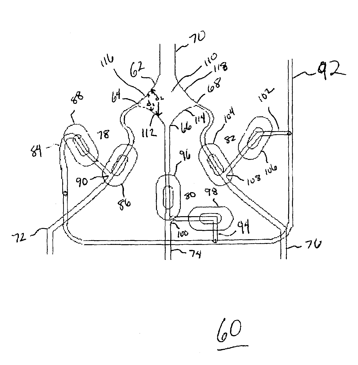
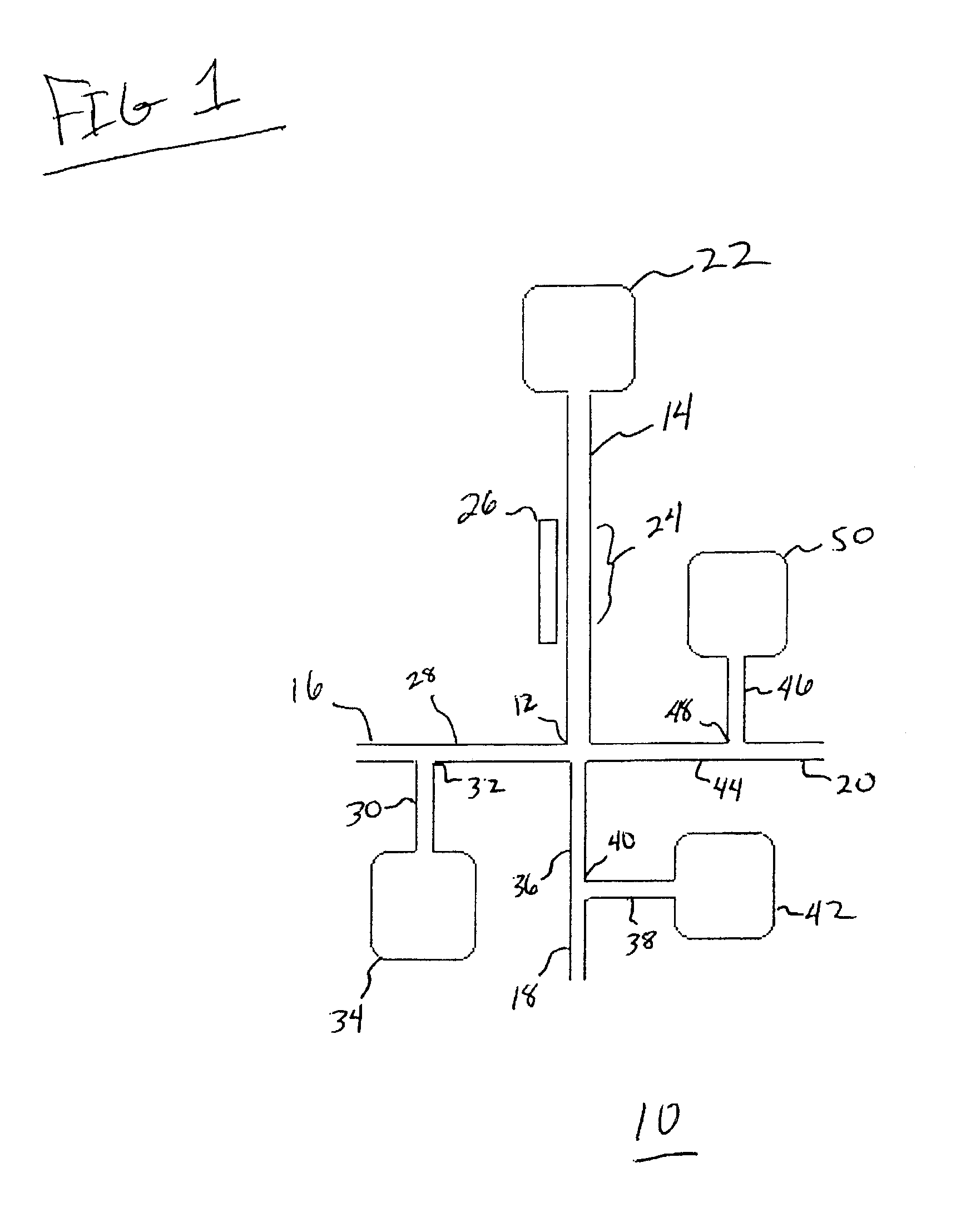
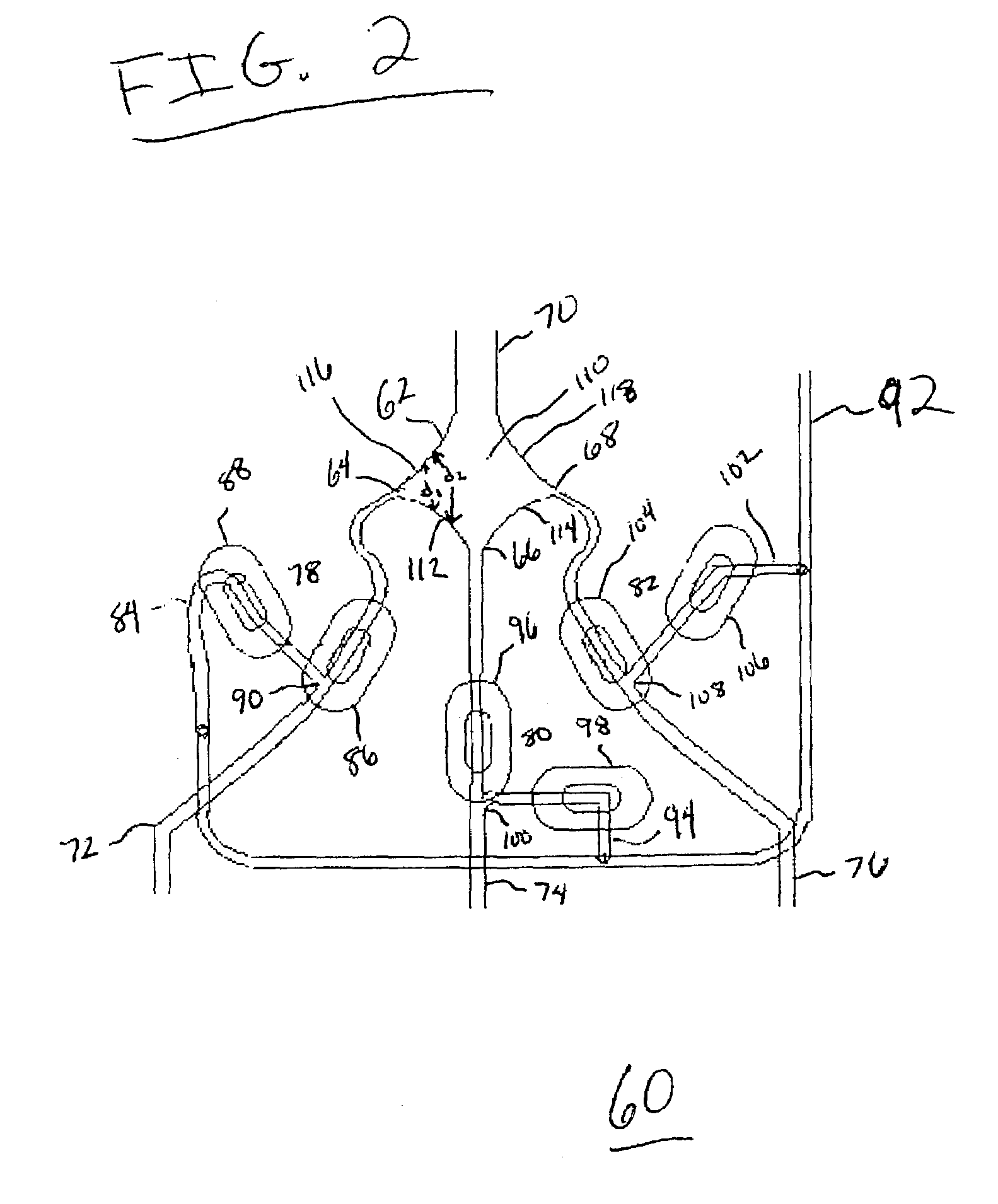
[0017]The invention is illustrated by the following preferred embodiments. In the drawings, like numbers refer to like features, and the same number appearing in more than one drawing refers to the same feature. The members of the flow system of this invention that are “connected” are fluidically connected. The term “between” refers to the fluidic positioning, which does not necessarily correspond to the geometric positioning. The terms “top”, “bottom” and “side” refer to the orientation in the drawings, which is not necessarily the orientation of the members in operation.

[0018]The term “microfluidic” is generally defined as a substrate having a fluid passage with at least one internal cross-sectional dimension that is less than 500 micrometers and typically between about 0.1 micrometers and about 500 micrometers. The term “channel” as used herein, refers to a microfluidic channel and describes fluid elements dimensioned so that flow therein is substantially laminar.

[0019]As used he...


PUM

PropertyMeasurementUnit
Areaaaaaaaaaaa
Hydrophilicityaaaaaaaaaa
Hydrophobicityaaaaaaaaaa

Abstract

Described herein is microfluidic device for joining fluids and a related method for doing the same. The device according to the present invention includes a microfluidic junction, an outlet channel, and a plurality of circuit units. A microfluidic junction is an area for converging multiple fluids. An outlet channel is capable of receiving fluid from the microfluidic junction. An outlet channel includes a first end connected with the microfluidic junction, a second end connected with a waste reservoir, and an analysis region positioned between the first end and the second end of the outlet channel. The device also includes a plurality of circuit units. Each circuit unit includes a source channel with a first end capable of receiving sample fluid and a second end connected with the microfluidic junction; a branch channel connected with the source channel at an intersection; and a flow diversion system capable of differentially directing fluid flowing through a source channel either into the microfluidic junction or into a branch channel.

Description

CROSS-REFERENCE TO RELATED APPLICATIONS[0001]This application claims priority from U.S. Provisional Patent Application No. 60 / 364,343, filed Mar. 14, 2002, entitled “Microfluidics Systems and Methods”.FIELD OF THE INVENTION[0002]This invention relates to microfluidic devices and methods for performing analytical testing, and in particular, to a group of devices and methods that use microfluidic technology to join and analyze multiple fluids.BACKGROUND OF THE INVENTION[0003]Microfluidic devices are becoming increasingly popular for performing analytical testing. Tools developed by the semiconductor industry for miniaturizing electronics enable fabrication and inexpensive mass production of intricate fluid systems. Microfluidic systems are increasingly utilized in performing a variety of analytical techniques for the acquisition of information in multiple disciplines, including the medical field, life sciences, and drug discovery and development.[0004]There are different ways to manuf...

Claims


Application Information

Patent Timeline
IPC IPC(8): B01L3/02B01L11/00B32B27/04B32B27/12B32B5/02G01N35/08B01J19/00B01L3/00B01L99/00C12M1/00G01N15/14G01N37/00
CPCG01N15/1404B01L2200/0636B01L2300/0627B01L2300/0861B01L2300/0864Y10T436/117497Y10T436/118339Y10T436/2575Y10T436/11Y10T436/25375G01N2015/149
Inventor HAYENGA, JON W.WEIGL, BERNHARD H.BARDELL, RONALD L.MORRIS, CHRISTOPHER J.
Owner PERKINELMER HEALTH SCIENCES INC
Why Eureka
Try Eureka