Attachment and optical probe

a technology of optical probes and adhesives, applied in the field of optical probes, can solve the problems of avoiding conventional securing mechanisms that are often less than optimal, presenting adherence problems on surfaces of adhesive-based securing mechanisms, and affecting the stability of optical probes

Active Publication Date: 2007-05-29
JPMORGAN CHASE BANK NA
View PDF130 Cites 885 Cited by
  • Summary
  • Abstract
  • Description
  • Claims
  • Application Information

AI Technical Summary

Problems solved by technology

However, the foregoing conventional securing mechanisms are often less than optimal in certain environments.
For example, adhesive-based securing mechanisms can present adherence issues on surfaces that are wet and / or fluid-covered, such as infant skin immediately following birth.
For example, in the baby born at or near term, skin coatings such as vernix can present adhesion problems, and in the preterm infant, adhesive-based sensors can irritate the infant's fragile skin.
Moreover, hook-and-loop-based securing mechanisms, such as Velcro® straps, can be applied incorrectly.
In highly agitated environments, such as those associated with newborns, patient transport, exercise testing and ICU care, a multistep process is burdensome and often difficult for the clinician.
In addition to the forgoing infant concerns, environments including severely damaged and / or sensitive tissue, such as burns or the like, can pose a number of problems for the conventional securing mechanisms.
For example, adhesive-based securing mechanisms may affix themselves to fragile newly healed skin such that removal of the adhesive may cause the skin to tear, thereby redamaging the tissue and causing pain to the patient.
Spring-tension-based or pressure-based securing mechanisms, such as a clothespin-type clip mechanism, may not allow the skin to optimally breathe, may restrict blood flow and are often recommended for short-term application.
Although conventional securing mechanisms are often unworkable in the foregoing environments, the need for non-invasive monitoring in those environments remains.

Method used


Image

  • Attachment and optical probe
  • Attachment and optical probe
  • Attachment and optical probe

Examples


Embodiment Construction

[0010]Based on the foregoing, a need exists for a securing mechanism capable of functioning in environments where adhesive-based, spring-tension-based, and / or hook-and-loop-based securing mechanisms are often less effective.

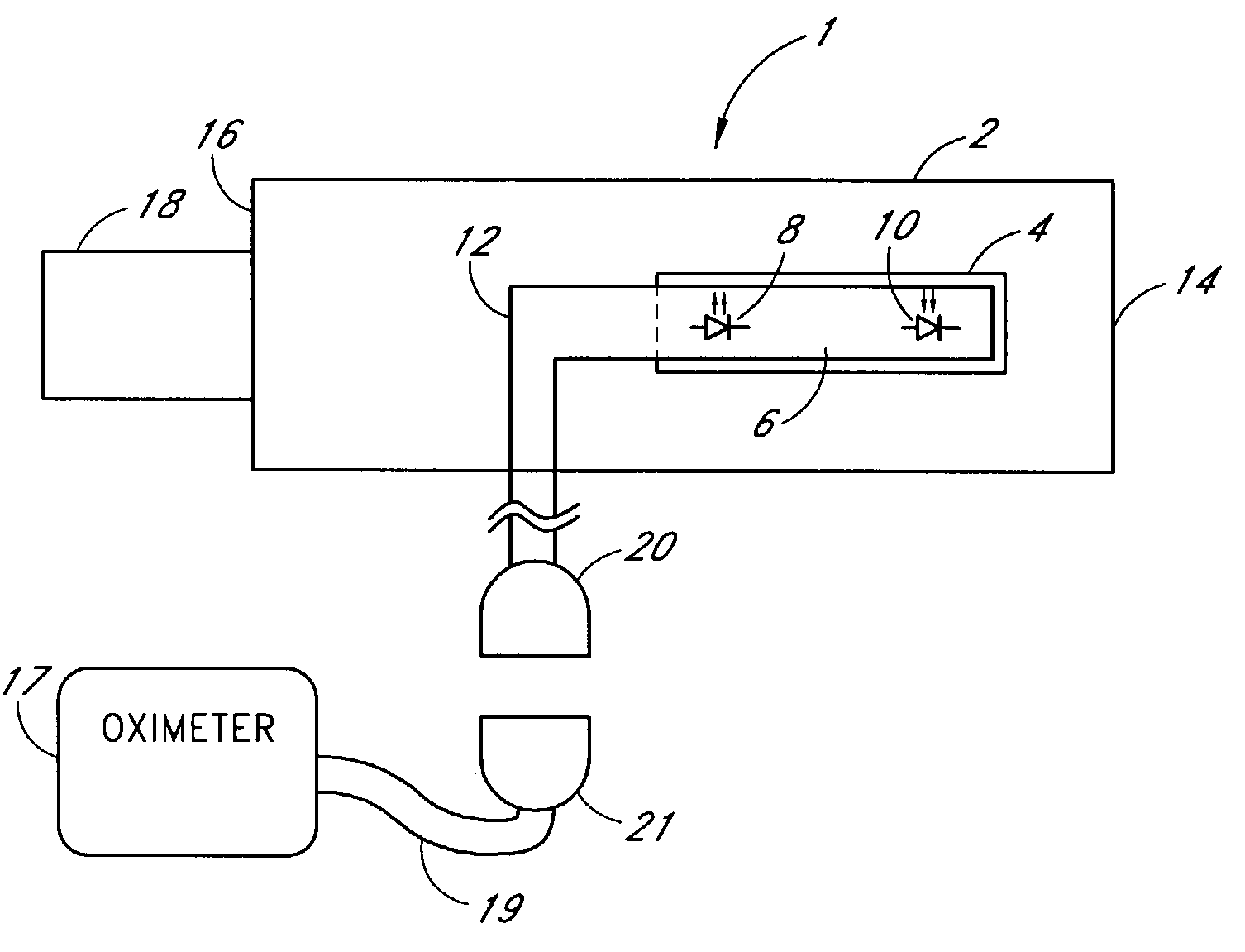
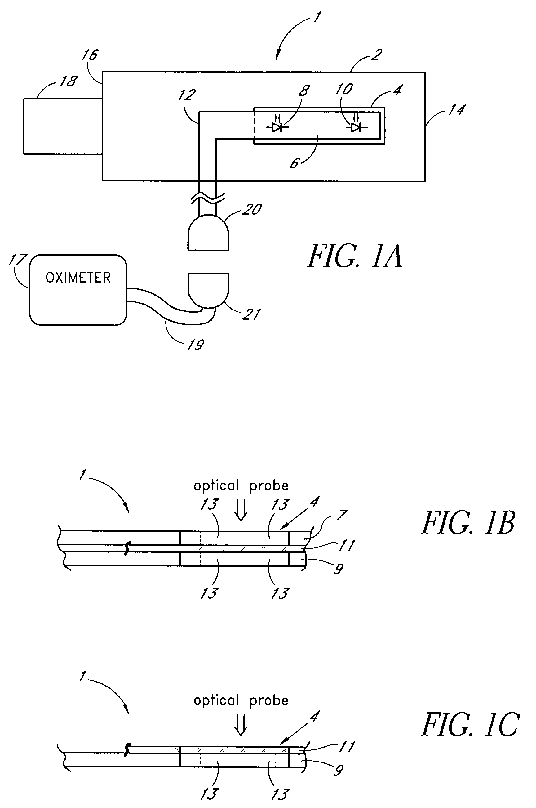
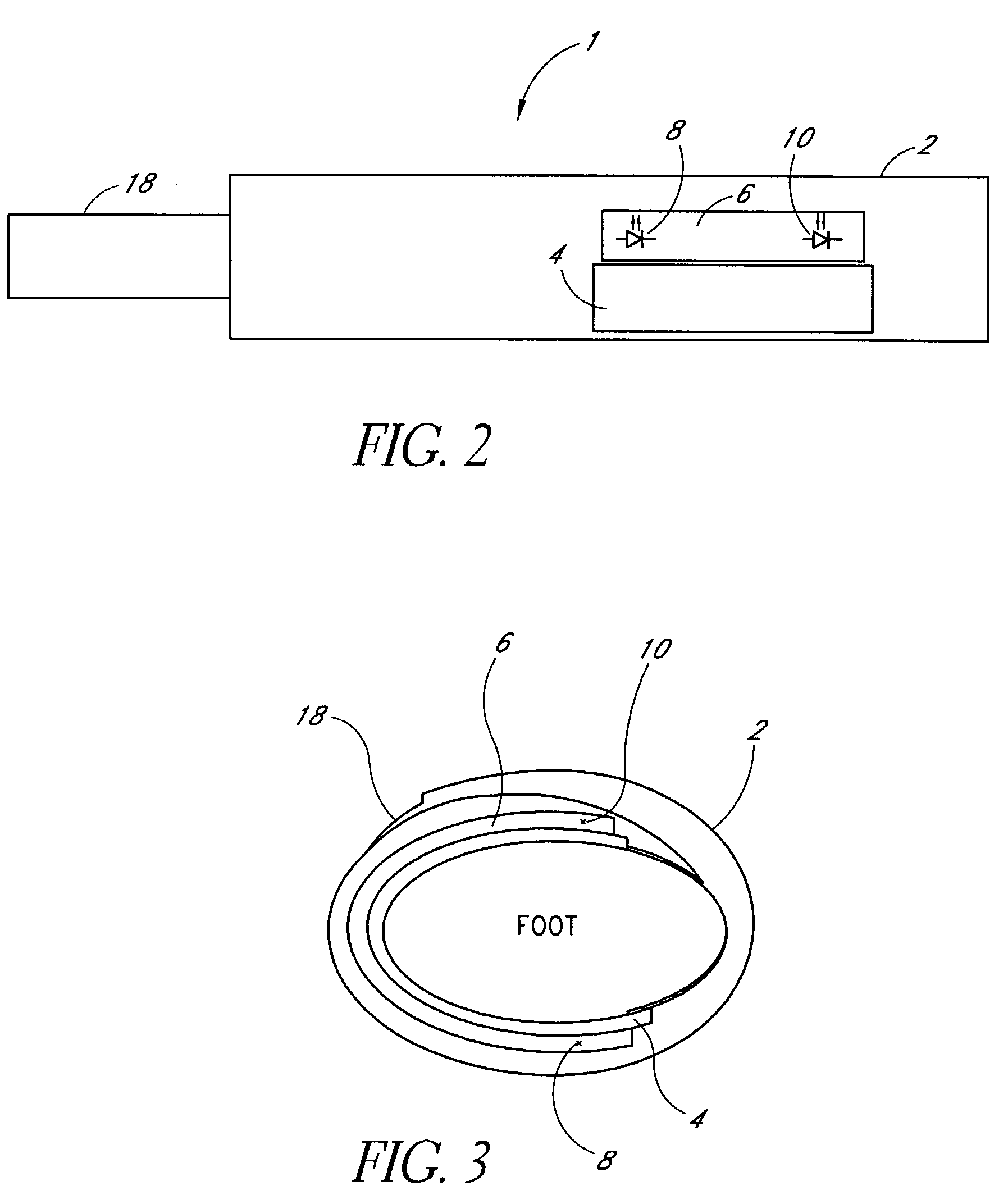
[0011]Accordingly, one aspect of an embodiment involves an attachment for securing an optical probe to a measurement site. The attachment has an elongated support with a first end and a second end, and a dedicated area in proximity of the first end. The dedicated area receives an optical probe and includes a material that is transparent for light emitted and received by the optical probe. The dedicated area mountably receives the optical probe on the material so that in use, the material is positioned between the optical probe and a surface of a measurement site.

[0012]The optical probe may be factory-mounted to the dedicated area of the attachment as a ready-to-use sensor or probe. In the alternative, the attachment may be available as an individual component, or...


PUM


Abstract

A medical monitoring system, such as an oximetry system, applies an attachment for securing an optical probe to a measurement site. The attachment has an elongated support with a first end and a second end, and a dedicated area in proximity of the first end. The dedicated area receives an optical probe and includes a material that is transparent for light emitted and received by the optical probe. The dedicated area mountably receives the optical probe on the material so that in use, the material is positioned between the optical probe and a surface of a measurement site. The optical probe may be factory-mounted to the dedicated area of the attachment as a ready-to-use sensor. In the alternative, the attachment may be available as an individual component, or as a part of a kit including the attachment and the optical probe.

Description

BACKGROUND OF THE INVENTION[0001]1. Field of the Invention[0002]Embodiments of the present invention relate in general to optical probes that are secured to a measurement site during use. More particularly, the embodiments relate to optical probes that are secured to the measurement site by wrapping.[0003]2. Description of the Related Art[0004]An optical probe generally operates by measuring a light signal passed through a medium. In oximetry, the optical probe attaches to an oximeter system such that the oximeter system determines at least one characteristic of the medium. In the medical field, a pulse oximetry probe measures a light signal passed through tissue. For example, after passing through tissue, the light signal varies depending on the oxygen saturation of the blood in that tissue. The oximeter system processes the measured light signals from the pulse oximetry probe and can determine characteristics of the tissue, including, for example, a pulse rate, blood oxygen satura...

Claims


Application Information

Patent Timeline
Patent Type & Authority Patents(United States)
IPC IPC(8): A61B5/00
CPCA61B5/14552
Inventor AL-ALI, AMMARGRUNHAGEN, ANGELA
Owner JPMORGAN CHASE BANK NA
Why Eureka
Try Eureka