Pressure sensor
a technology of pressure sensor and pressure sensor, which is applied in the direction of fluid pressure measurement by mechanical elements, fluid pressure measurement using elastically deformable gauges, instruments, etc., and can solve problems such as redundancy in the progress of wear
- Summary
- Abstract
- Description
- Claims
- Application Information
AI Technical Summary
Benefits of technology
Problems solved by technology
Method used
Image

Examples
first embodiment
(First Embodiment)
[0035]Hereafter, the first embodiment of the present invention will be described with reference to the accompanying drawings. A pressure sensor described in this embodiment is used in a place where the pressure sensor suffers vibrations of several kHz, for example, in an engine room of a vehicle, and the like.
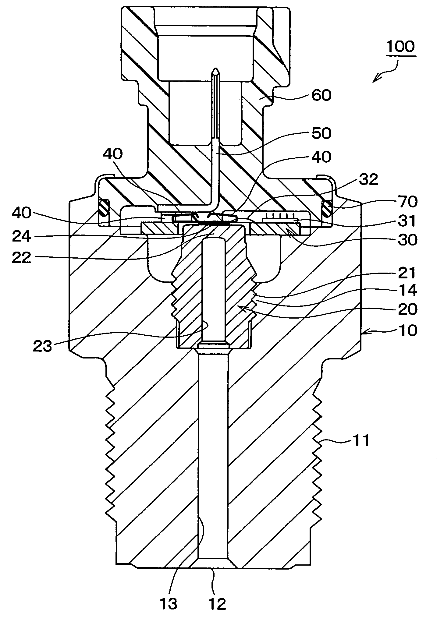
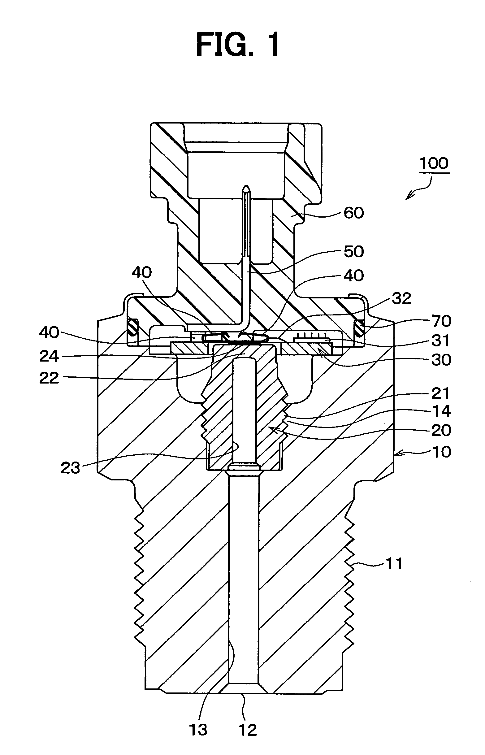
[0036]FIG. 1 is a schematic sectional view of a pressure sensor 100 in the first embodiment. As shown in this drawing, the pressure sensor 100 is so constructed as to include a housing 10, a stem 20, a substrate 30, a spring terminal 40, a terminal 50, and a connector case 60.
[0037]The housing 10 is a hollow case made of metal and worked by cutting, cold forging, or the like, and has a threaded portion 11, which can be connected to a body to be measured by screw coupling. The threaded portion 11 is formed on the outer peripheral surface of one end side of the housing 10. A hole extending from an opening 12 formed in one end of the housing 10 to the other end o...
second embodiment
(Second Embodiment)
[0055]In this embodiment, only portions different from the first embodiment will be described. This embodiment is different from the first embodiment in that the spring terminal 40 is bonded to the terminal 50.
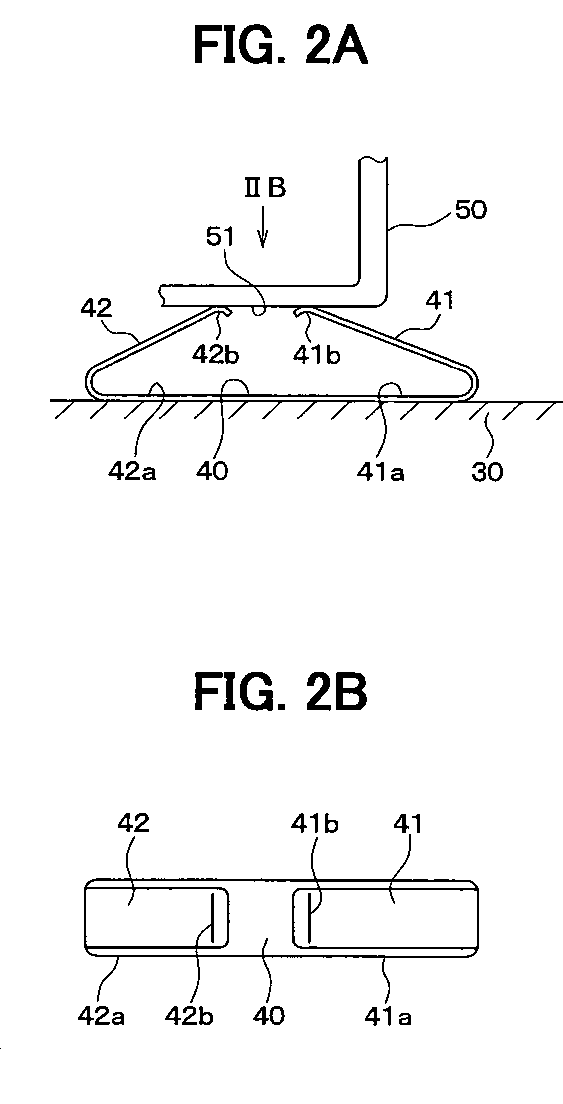
[0056]FIGS. 3A and 3B are schematic views of the spring terminal 40 in this embodiment, in which FIG. 3A is a schematic view of the vicinity of the spring terminal 40 and FIG. 3B is a view of the substrate 30 when viewed from the connector contact 60 side.
[0057]As shown in FIG. 3A, the spring terminal 40 is in the state where it is bonded to the bottom portion 51 of the terminal 50. The spring terminal 40 is bonded to the bottom portion 51 of the terminal 50, for example, by resistance welding. Here, as to the spring terminal 40 used in this embodiment, the same part as in the first embodiment is employed.
[0058]Moreover, as shown in FIG. 3B, the substrate 30 has electrodes 33 arranged thereon in such a way that the electrodes 33 are electrically connected vi...
third embodiment
(Third Embodiment)
[0063]In this embodiment, only portions different from the first embodiment and the second embodiment will be described. In the above first and second embodiments, the spring terminal 40 in which the respective spring portions 41, 42 have different natural frequencies is employed. However, in this embodiment, a spring terminal in which the respective spring portions have the same natural frequency characteristic is used and this spring terminal is changed in the state of arrangement, so that the frequencies, at which the respective spring portions resonate with the external vibrations, are set different from each other. Hereafter, this will be described with reference to FIG. 4.
[0064]FIG. 4 is a schematic view of the vicinity of a spring terminal 43 in accordance with this embodiment. First, in this embodiment, the spring terminal 43 is constructed of a single metal plate and has a structure in which both sides of the metal plate are bent to form a plurality of, th...
PUM
| Property | Measurement | Unit |
|---|---|---|
| thickness | aaaaa | aaaaa |
| width | aaaaa | aaaaa |
| width | aaaaa | aaaaa |
Abstract
Description
Claims
Application Information