Double clutch transmission

a transmission and clutch technology, applied in the direction of mechanical equipment, transportation and packaging, gearing, etc., can solve the problem of difficulty in accommodating additional gear stages

Inactive Publication Date: 2007-06-05
DAIMLER AG
View PDF13 Cites 97 Cited by
  • Summary
  • Abstract
  • Description
  • Claims
  • Application Information

AI Technical Summary

Benefits of technology

[0004]In a double clutch transmission in which an input shaft can be coupled by two load clutches selectively with a central intermediate shaft and a concentric intermediate shaft and each of the intermediate shafts can be operatively connected by gear stages selectively to a first or a second jackshaft arranged in the power output path to a driven vehicle axle, wherein the jackshafts are arranged parallel to the transmission input and intermediate shafts, the intermediate shafts each have at least one gear firmly mounted thereon which forms the input gear for more than one of the gear stages provided for different transmission gear ratios so as to form a compact transmission arrangement, particularly for transverse engine applications.
[0010]A gear structure connected to the first jackshaft and the third jack shaft can be arranged in a common plane extending normal to the rotational axis, thereby providing for a short transmission arrangement.
[0013]Preferably, the two gear change clutches of the connected gear stages of the central intermediate shaft are arranged on the first and second jackshaft together with a gear structure of an odd numbered forward gear in a space saving manner.
[0021]The double clutch transmission according to the invention provides for a compact design particularly a short length of the transmission which makes the transmission particularly suitable in connection with transverse engine applications.

Problems solved by technology

With this arrangement, it is difficult to accommodate additional gear stages if more than six forward gears are to be provided since then at least one additional odd numbered gear arrangement would have to be provided by an additional gear stage which would have to be connected to the central intermediate shaft that is already connected to three gear stages.

Method used


Image

  • Double clutch transmission
  • Double clutch transmission
  • Double clutch transmission

Examples


Embodiment Construction

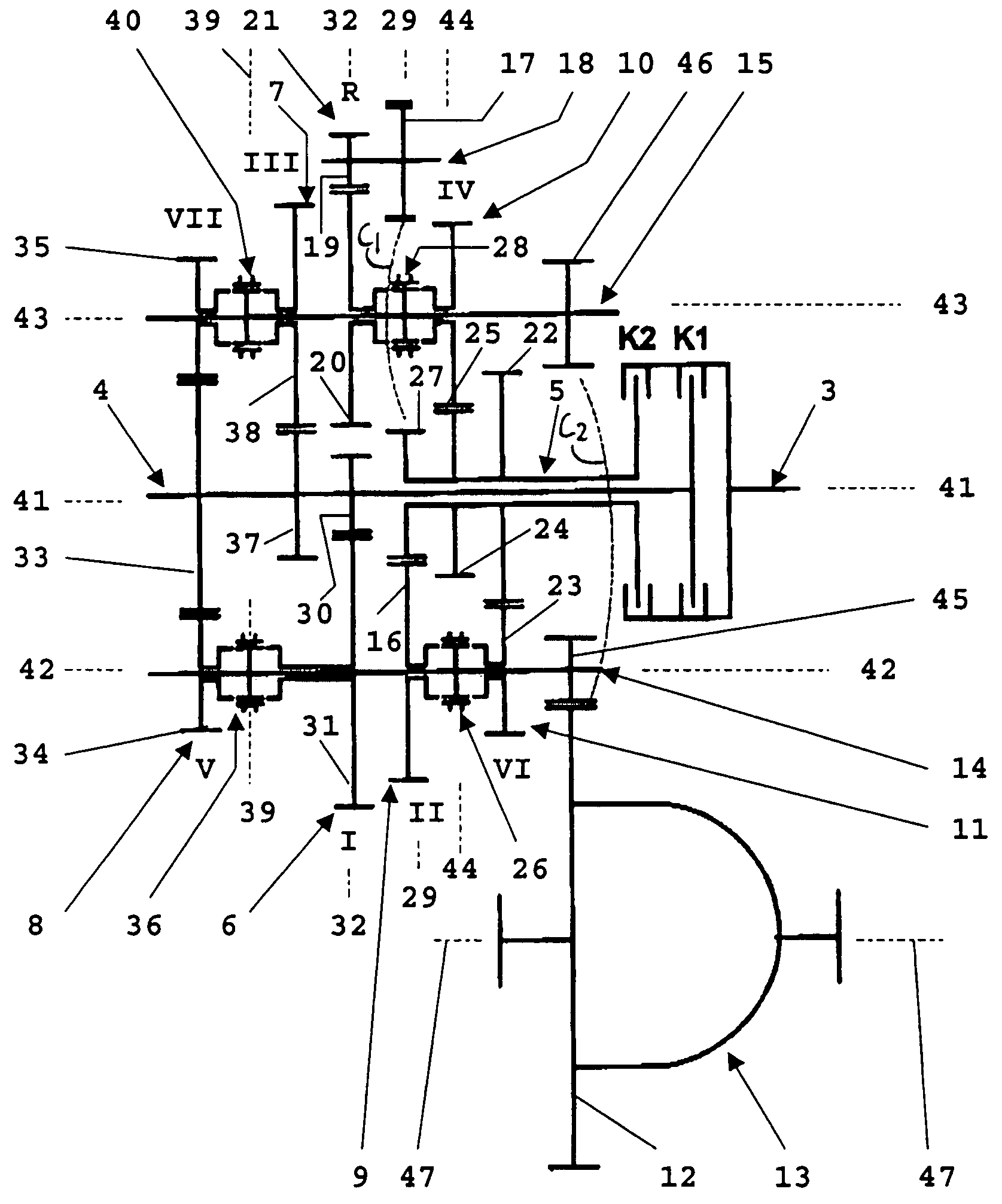
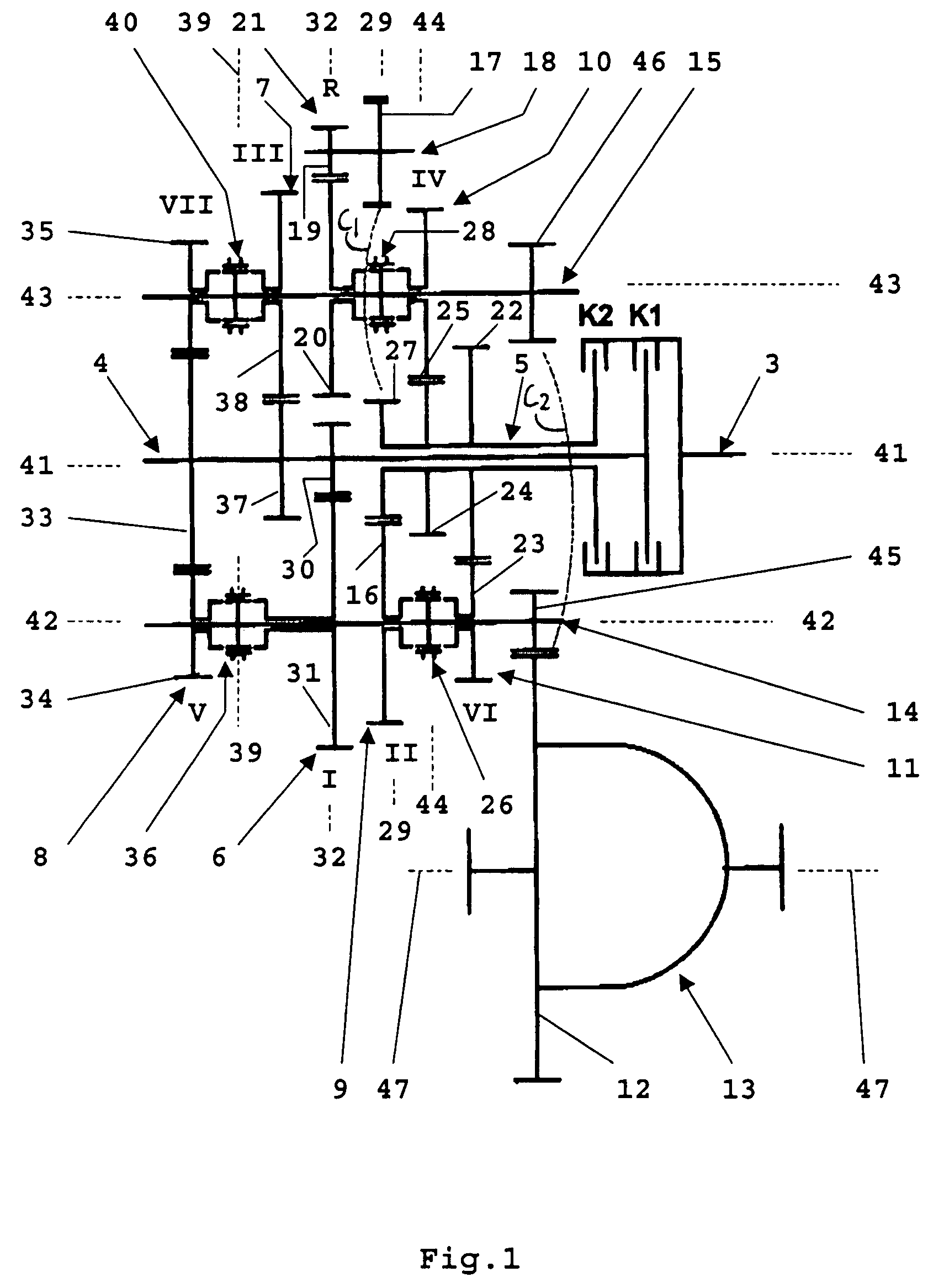
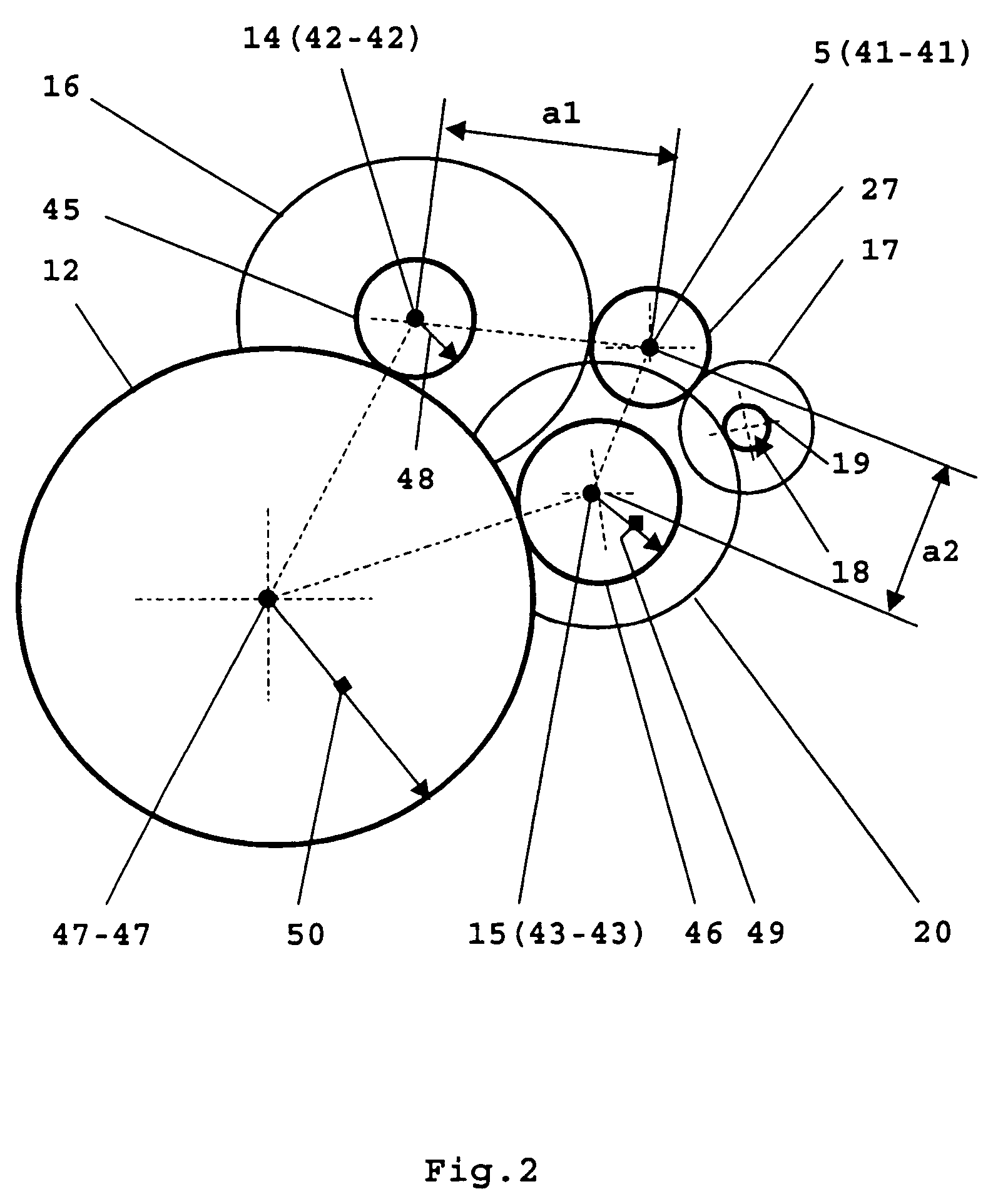
[0031]The transmission includes an input shaft 3 which is driven by an engine. The input shaft 3 can be coupled by a first load clutch K1 to an intermediate center shaft 4 and, by a second load clutch K2 to an intermediate shaft 5 which is concentric with the intermediate center shaft 4. Parallel to, and spaced from, the input shaft 3 and also spaced from one another a first jackshaft 14 and a second jackshaft 15 as well as a third jackshaft 18 are arranged. On the first jackshaft 14, a drive gear 45 is firmly mounted for rotation therewith, which is in engagement with a gear ring 12 of a differential wheel drive 13. On the second jackshaft 15, another drive gear 46 is supported for rotation with the second jackshaft 15 which is also in engagement with the gear ring 12 of the differential wheel drive 13.

[0032]The central intermediate shaft 14 is provided with a simple gear stage 6 forming the gear structure for the first forward gear, I. gear, whose input gear 30 is firmly mounted o...


PUM


Abstract

In a double clutch transmission in which an input shaft can be coupled by two load clutches selectively with a central intermediate shaft and a concentric intermediate shaft and each of the intermediate shafts can be operatively connected by gear stages selectively to a first or a second jackshaft arranged in the power output path to a driven vehicle axle, wherein the jackshafts are arranged parallel to the transmission input and intermediate shafts, the intermediate shafts each have at least one gear firmly mounted thereon which forms the input gear for more than one of the gear stages provided for different transmission gear ratios so as to form a compact transmission arrangement, particularly for transverse engine applications.

Description

BACKGROUND OF THE INVENTION[0001]The invention relates to a double clutch transmission in which an input shaft can be coupled by two load clutches selectively with a central intermediate and a concentric intermediate shaft and each of the intermediate shafts can be operatively connected to a first or a second jackshaft for transferring power at different transmission ratios.[0002]In such double clutch transmissions as disclosed for example in DE 198 21 164 A1, the transmission gear structure engaged for forming the reverse transmission gear setup is connected to the central intermediate shaft and, additionally, forms the transmission gear setup for the first forward gear (I. gear). The known double clutch transmission includes six forward gears of which the transmission structure for the even number gears IV and VI are formed by an engaged gear arrangement and the even number gear II is formed by a simple gear structure and both are connected to the concentric intermediate shaft. Co...

Claims


Application Information

Patent Timeline
Patent Type & Authority Patents(United States)
IPC IPC(8): F16H3/38B60K17/08F16H3/00F16H3/08F16H3/093
CPCF16H3/006F16H3/093F16H2003/0931F16H2200/0056Y10T74/19223Y10T74/19228Y10T74/19284Y10T74/19405Y10T74/19233Y10T74/19288Y10T74/194
Inventor GITT, CARSTEN
Owner DAIMLER AG
Why Eureka
Try Eureka