Long life fan motor

a fan motor and long-life technology, applied in the direction of magnetic circuit rotating parts, piston pumps, magnetic circuit shapes/forms/construction, etc., can solve the problems of increasing limiting the higher performance of the fan motor, etc., to achieve the effect of reducing the temperature difference, reducing the heat generated in the windings, and improving the cooling efficiency of the windings

Active Publication Date: 2007-06-05
SANYO DENKI CO LTD
View PDF11 Cites 18 Cited by
  • Summary
  • Abstract
  • Description
  • Claims
  • Application Information

AI Technical Summary

Benefits of technology

[0004]An object of the present invention is therefore to provide a fan motor that can reduce an increase in the temperature of members in a cup-like member therein and thereby can achieve higher performance of the fan motor.
[0005]Another object of the present invention is to provide a fan motor that can extend the life of the bearings of the fan motor by reducing the amount of heat transferred to the bearings.
[0006]Yet another object of the present invention is to provide a fan motor that can prevent foreign matters from entering the inside of the motor through vent holes therein.

Problems solved by technology

However, if the number of revolutions of the motor is increased as described above, the amount of heat generated in the windings increases.
For this reason, because of the need for suppressing the increase in the temperature of the bearings, the higher performance of the fan motor was conventionally hindered.

Method used


Image

  • Long life fan motor
  • Long life fan motor
  • Long life fan motor

Examples


Embodiment Construction

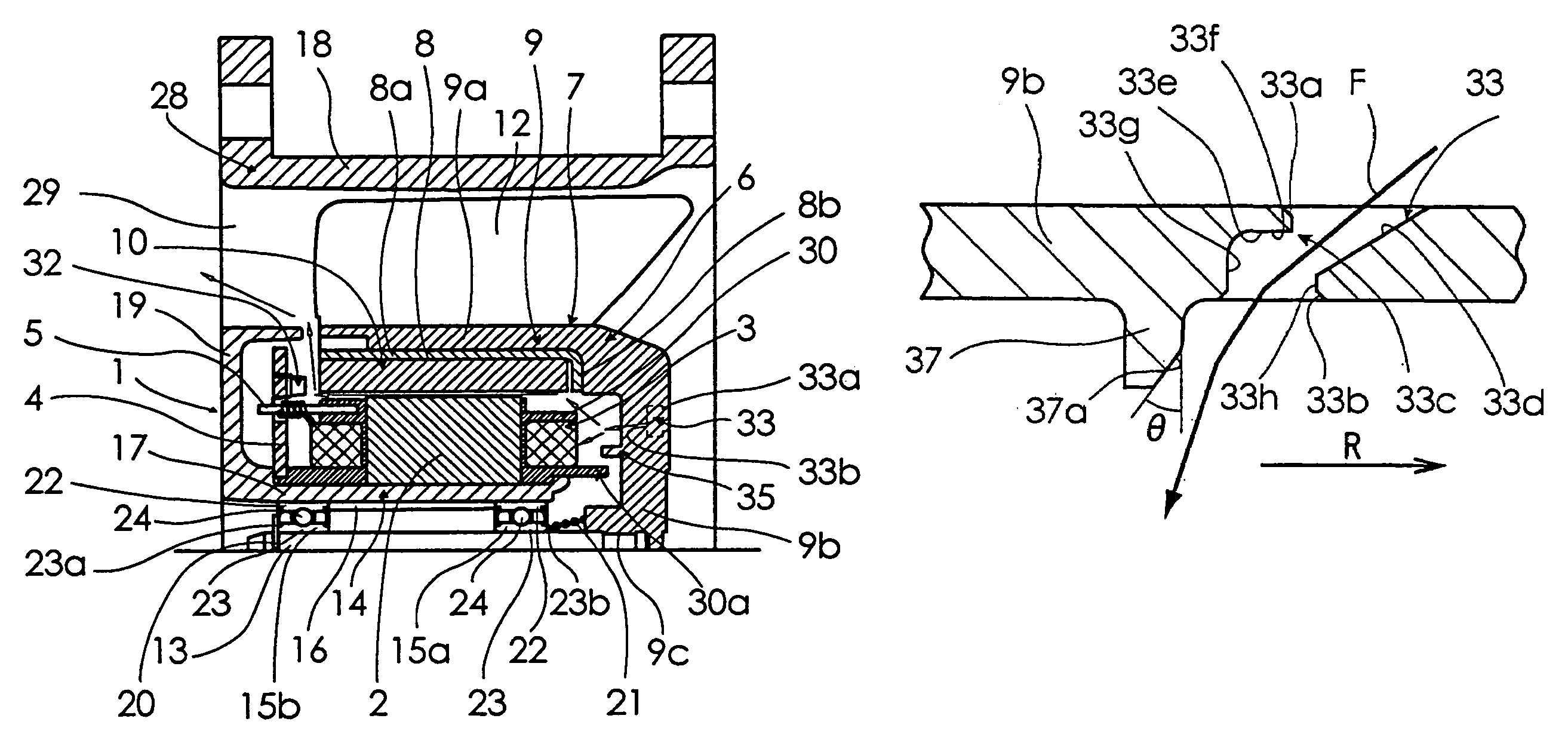
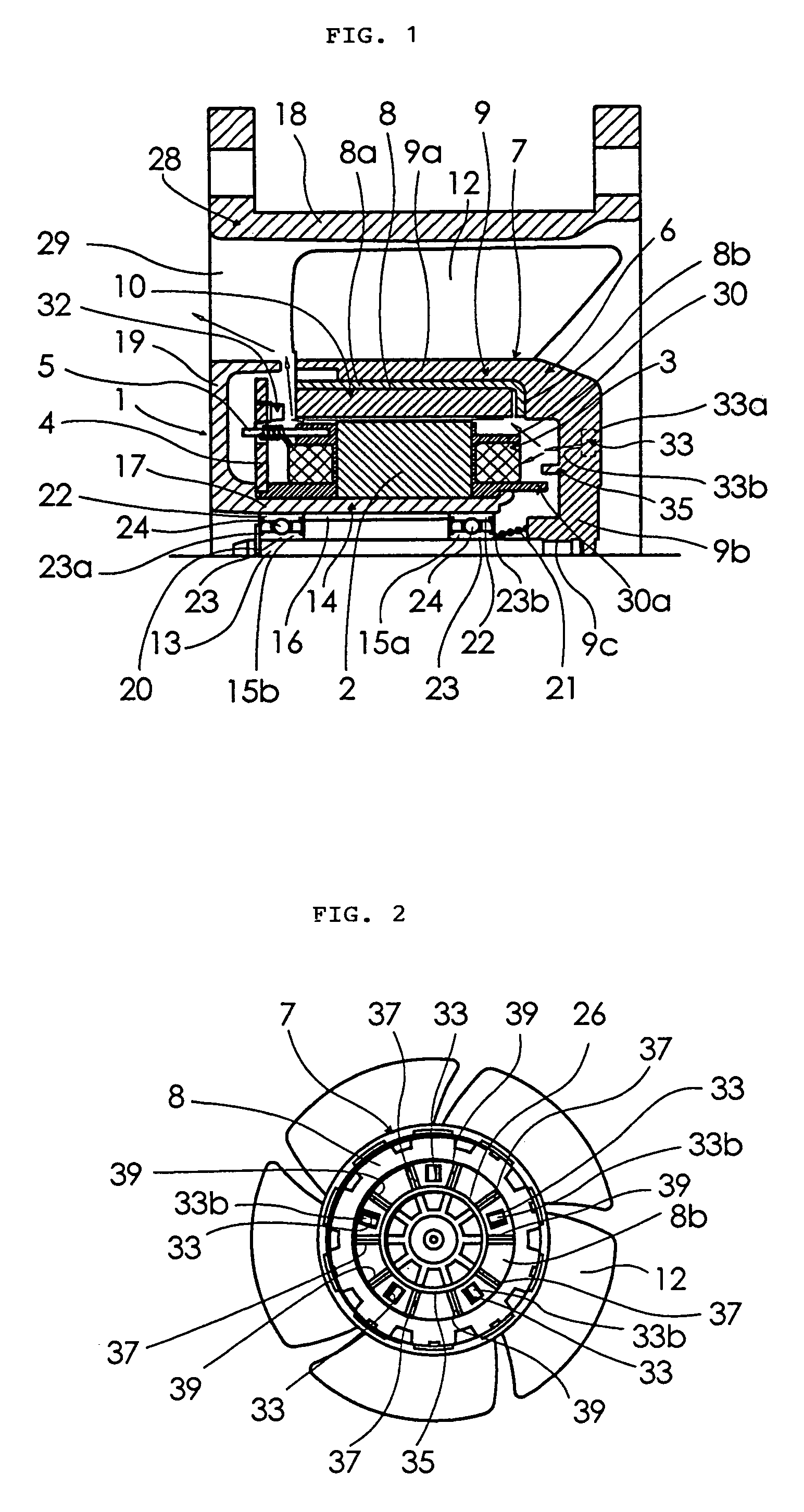
[0023]The best mode for carrying out the present invention will be described below with reference to the accompanying drawings. FIG. 1 is a vertical cross sectional view showing a half portion of a fan motor according to an embodiment of the present invention. Referring to FIG. 1, the fan motor according to this embodiment includes a stator 1, a circuit substrate 4, a stator side case 14, and a rotor 6. The stator 1 includes an iron core 2 constituted from a plurality of laminated silicon steel plates. The iron core 2 has a plurality of projecting pole portions arranged in a circumferential direction thereof. A winding is wound around each projecting pole portion of the iron core 2 through an insulator 30, thereby forming windings 3 as a whole. These projecting pole portions function as stator magnetic poles when the windings 3 are excited. The tip end of each projecting pole portion becomes the pole face of each stator magnetic pole.

[0024]The circuit substrate 4 is arranged on the ...


PUM


Abstract

There is provided a fan motor in which an increase in the temperature of windings thereof is surpressed, thereby achieving a long life and high performance. Vent holes 33 for introducing air into a cup-like member 9 are formed in a bottom wall section 9b of a rotor 6. Air flowing direction adjusting ribs 37, which are arranged at intervals in a peripheral direction and each of which extends in a radial direction, are integrally provided on the inner surface of the bottom wall section 9 so that air flown out of exits 33b of the vent holes 33 is directed toward windings 3. In addition to the air flowing direction adjusting ribs 37, a plurality of air stirring ribs 39 for stirring the air inside the cup-like member 9 is arranged on the inner surface of the bottom wall section 9.

Description

BACKGROUND OF THE INVENTION[0001]The present invention relates to a fan motor employed for cooling an electronic device or the like.[0002]Japanese Patent Application Laid-Open Publication No. 191611 / 1998 discloses a fan motor including a cup-like member and an impeller. The cup-like member has a cylindrical section with a plurality of rotor magnetic poles on an inner peripheral side thereof and a bottom wall section that blocks one end of the cylindrical section. The impeller includes a plurality of blades arranged outside the cylindrical section. In the fan motor of this type, in order to increase the volume of airflow and static pressure performance to aim at its higher performance, input power to windings is increased. The number of revolutions of the motor is thereby increased.[0003]However, if the number of revolutions of the motor is increased as described above, the amount of heat generated in the windings increases. Then, when this heat generation causes the heat to be trans...

Claims


Application Information

Patent Timeline
Patent Type & Authority Patents(United States)
IPC IPC(8): H02K9/06F04D25/02F04D25/08H02K7/14H02K9/04H02K29/00H02K1/27H02K9/02
CPCF04D25/082H02K1/2786H02K7/14H02K9/06F04D29/5806H02K1/2791
Inventor KUDO, NARUHIKOKURIBAYASHI, HIROMITSUNISHIZAWA, TOSHIYA
Owner SANYO DENKI CO LTD
Why Eureka
Try Eureka