

Light-emitting device
A technology for light-emitting devices and light-emitting diodes, which is applied to electric solid-state devices, semiconductor devices, electrical components, etc., can solve problems such as troublesome filling steps, and achieve the effect of reducing temperature
- Summary
- Abstract
- Description
- Claims
- Application Information
AI Technical Summary
Problems solved by technology
Method used
Image

Examples
Embodiment Construction
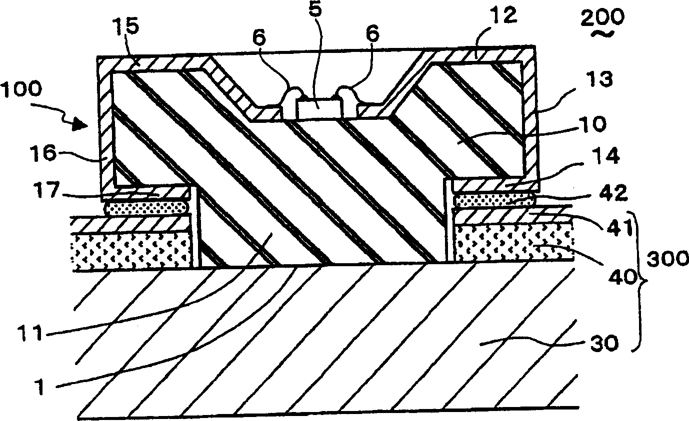
[0093] Light emitting devices of several embodiments of the present invention are explained below with reference to the accompanying drawings, wherein like reference characters denote like or corresponding parts throughout the several views.
[0094] figure 2 A light emitting device 200 of an embodiment of the present invention is shown. In the light emitting device 200 , the bottom 11 of the submount 100 for LEDs is in thermal contact with the metal plate 30 of the circuit board 300 . The submount 100 has a mounting base 10 having wires 12-14 and 13-17, and a light emitting diode (LED) chip 5 mounted on the mounting base 10. LED wafer 5 is shown along perpendicular to its figure 2 The orientation of the paper is issued for the harness. The circuit board 300 has a metal plate 30 and a metal pattern 41 for an electrical conductor formed on an electrical insulating layer 40 . The LED chip 5 has a gallium nitride semiconductor. In this embodiment and the following embodime...
PUM
 Abstract
Description
Claims
Application Information