
Method and apparatus for performing sample rate conversion

a sample rate and conversion method technology, applied in the field of digital communications, can solve the problem that the configuration shown in fig. 2 cannot be easily implemented in softwar

Active Publication Date: 2007-06-05
ARRIS ENTERPRISES LLC
View PDF3 Cites 37 Cited by
  • Summary
  • Abstract
  • Description
  • Claims
  • Application Information

AI Technical Summary

Benefits of technology

Enables efficient hardware or software implementation of sample rate conversion without the need for output sampling rates twice the input rate, allowing for flexible sampling rate ratios and decoupling of upsampling stages from the final output rate, facilitating flexible digital modulator configurations.

Problems solved by technology

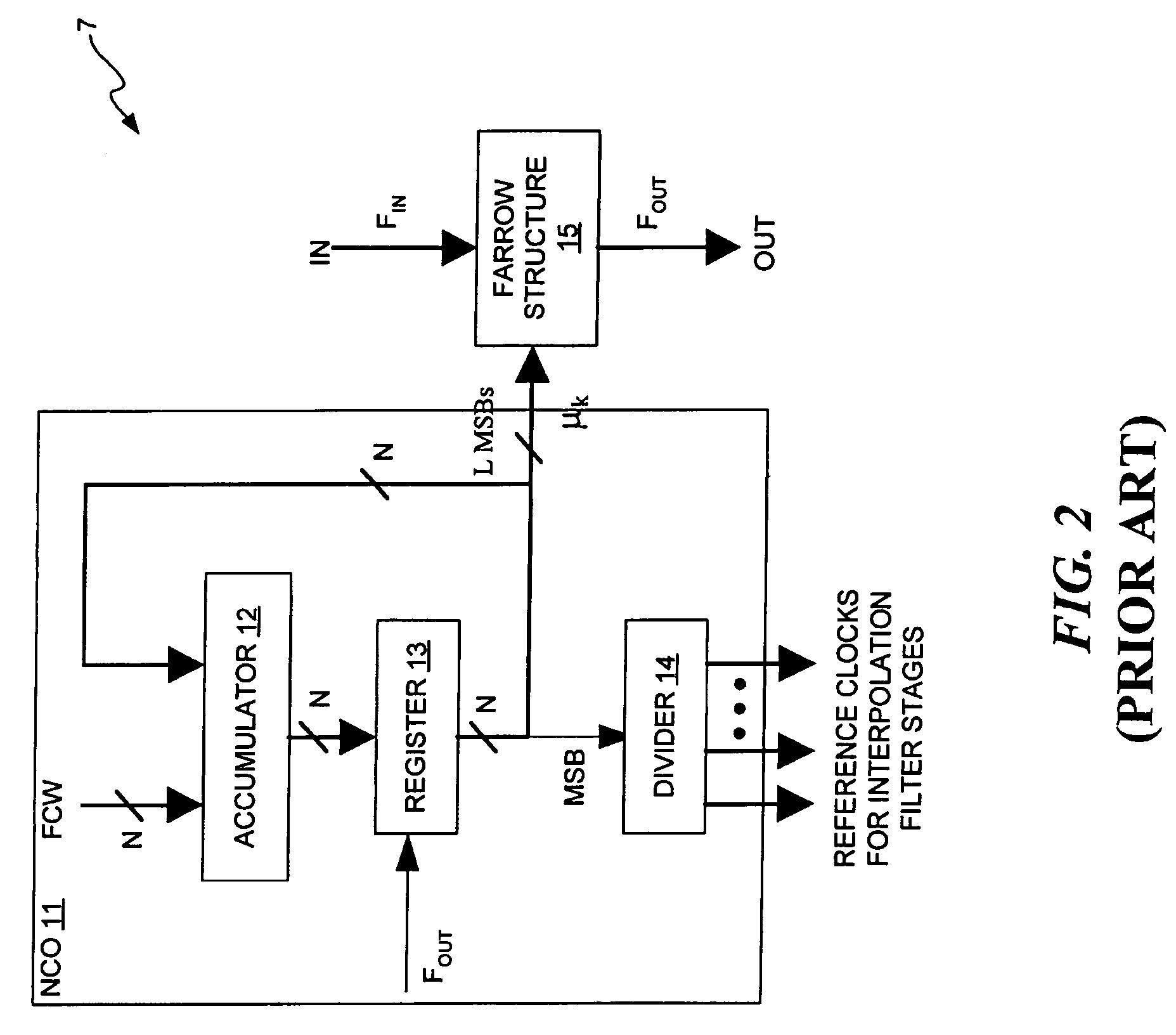
In addition, because each interpolation filter stage requires its own reference clock, the configuration shown in FIG. 2 cannot be easily implemented in software, if it can be implemented in software at all.

Method used


Image

  • Method and apparatus for performing sample rate conversion
  • Method and apparatus for performing sample rate conversion
  • Method and apparatus for performing sample rate conversion

Examples


Embodiment Construction

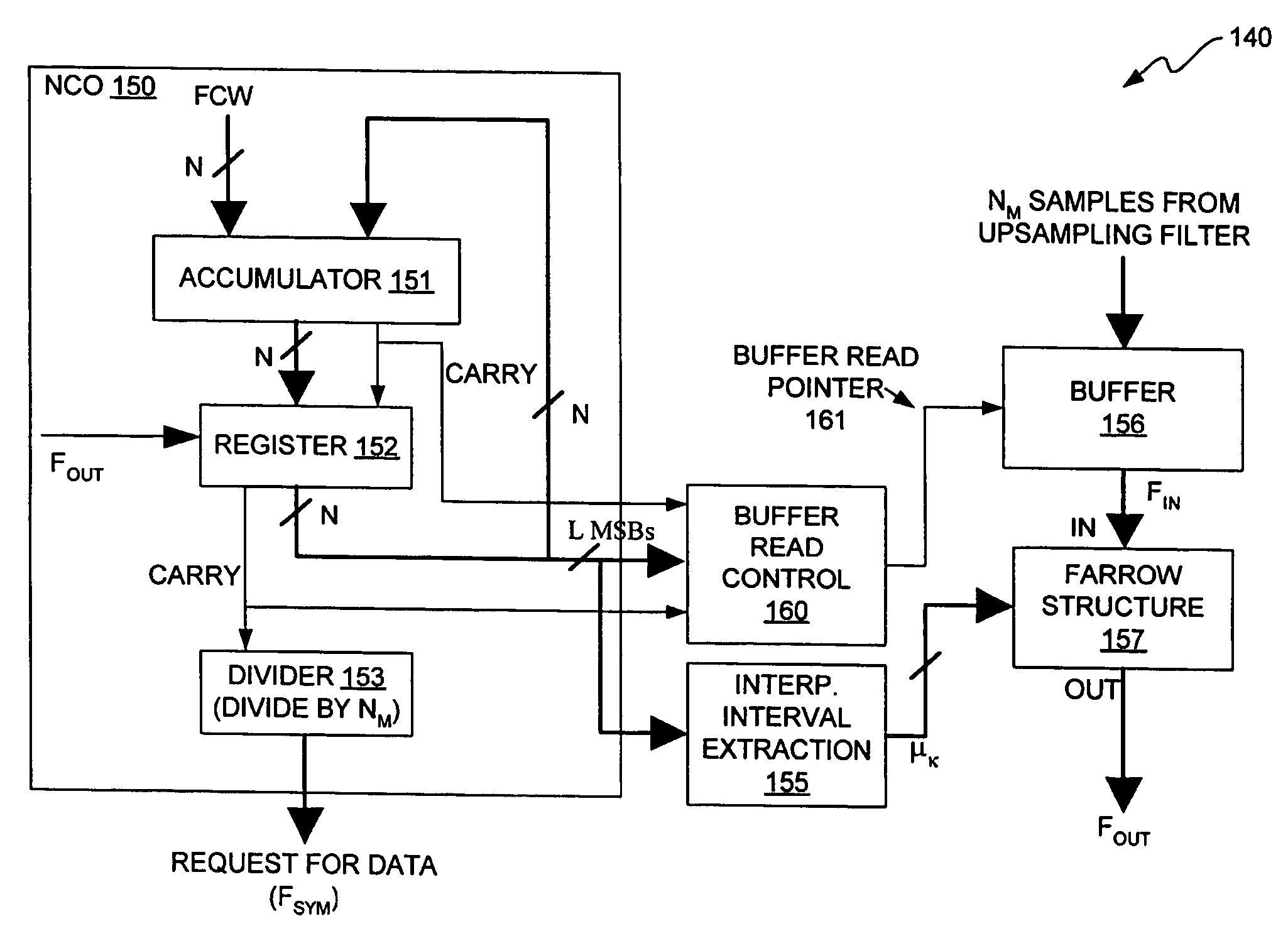
[0026]The invention provides a digital modulator having a sample rate converter that does not require that the final output sampling rate, FOUT, of the sample rate converter be at least twice as great as the input sampling rate, FIN, of the sample rate converter. In addition, the upsampling interpolation filter stages of the sample rate converter of the invention do not require any reference clocks to be provided by the NCO of the sample rate converter. Therefore, the upsampling interpolation filter stages are decoupled from the final output sampling rate, FOUT. This feature of the invention makes it feasible to implement the interpolation algorithms in software. Therefore, the interpolation algorithms may be implemented in software, hardware, or a combination of software and hardware. In addition, the polynomial-based interpolator of the Farrow Structure of the invention is capable of using an odd number of basepoints, although it is not required to use an odd number of basepoints....


PUM


Abstract

A digital modulator having a sample rate converter that does not require that the final output sampling rate, FOUT, of the sample rate converter be at least twice as great as the input sampling rate, FIN, of the sample rate converter. The upsampling interpolation filter stages of the sample rate converter of the invention do not require any reference clocks to be provided by the NCO of the sample rate converter. Therefore, the upsampling interpolation filter stages are decoupled from the final output sampling rate, FOUT. The interpolation algorithms may be implemented in software, hardware, or a combination of software and hardware. In addition, the polynomial-based interpolator of the Farrow Structure of the invention is capable of using an even or odd number of basepoints.

Description

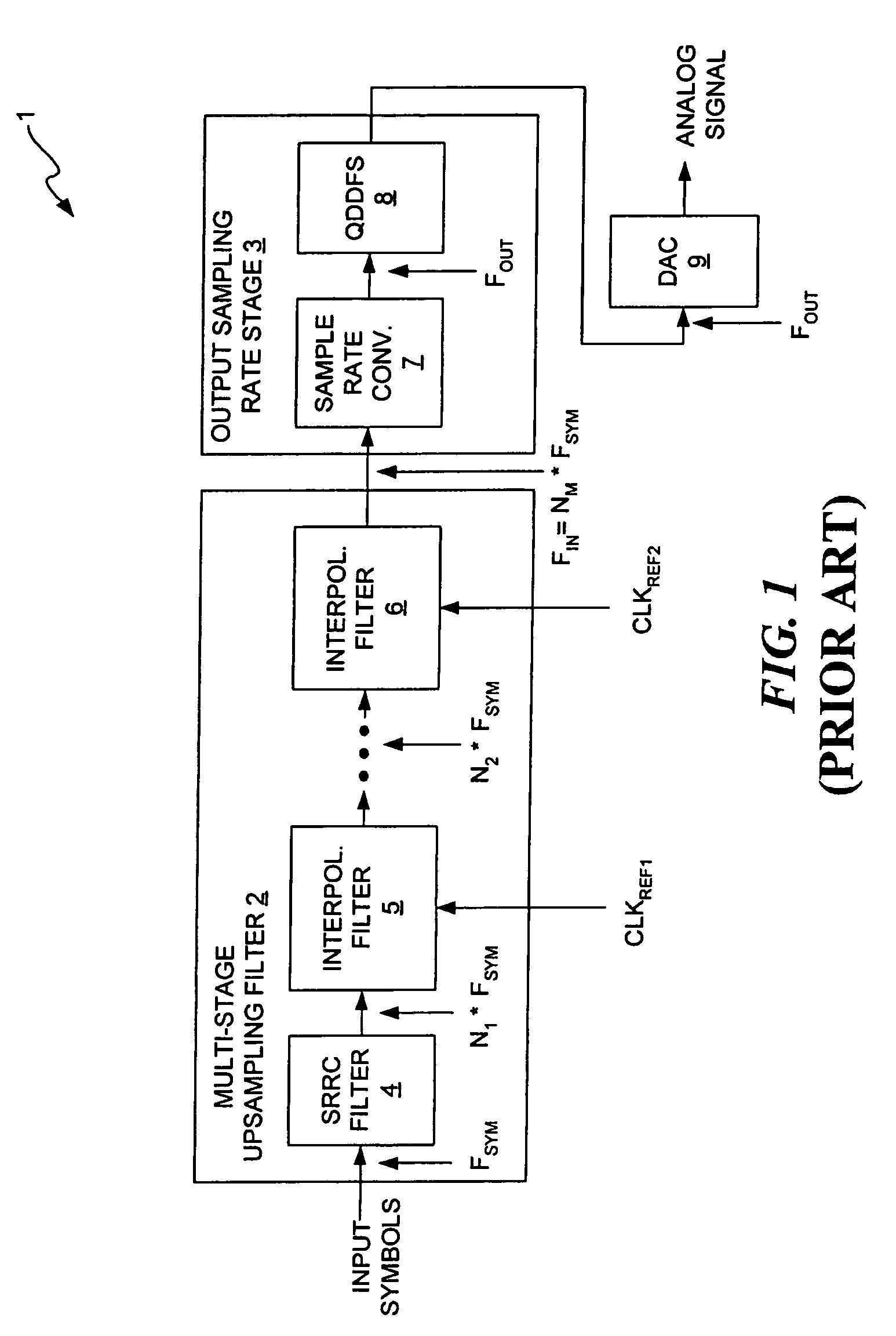
CROSS-REFERENCE TO RELATED APPLICATIONS[0001]This application claims priority to the filing date of a U.S. provisional patent application having Ser. No. 60 / 694,425, entitled “SAMPLE RATE CONVERTER FOR DIGITAL UNIVERSAL MODULATOR”, filed on Jun. 27, 2005, which is incorporated herein by reference in its entirety.TECHNICAL FIELD OF THE INVENTION[0002]The invention relates to digital communications and, more particularly, to performing sample rate conversion in a digital communications system.BACKGROUND OF THE INVENTION[0003]Digital modulators are widely used in digital communication systems, such as, for example, digital wireless systems and digital cable systems. Various standards govern the various types of communications systems. Each set of standards specifies a particular symbol rate to be used to transmit and receive information. FIG. 1 illustrates a block diagram of a known digital modulator 1. The digital modulator 1 has a multi-stage upsampling filter 2 and an output samplin...

Claims


Application Information

Patent Timeline
Patent Type & Authority Patents(United States)
IPC IPC(8): H03M7/00
CPCH03H17/028H03H17/0621
Inventor YE, ZHUAN
Owner ARRIS ENTERPRISES LLC
Learn More