Sampling rate conversion method and apparatus

a rate conversion and sampling rate technology, applied in the field of sampling rate conversion apparatus, can solve the problems of accumulating errors, unstable circuit operation, and inability to reproduce signals, and achieve the effect of high accuracy

Active Publication Date: 2005-07-28
RENESAS ELECTRONICS CORP
View PDF4 Cites 21 Cited by
  • Summary
  • Abstract
  • Description
  • Claims
  • Application Information

AI Technical Summary

Benefits of technology

[0010] In view of the above-depicted status of the art, it is an object of the present invention to provide a sampling rate conversion apparatus and a sampling rate conversion method by means of which conversion may be made to a high accuracy between two sampling rates which are based on two clocks differing in the frequency and in the generation sources.

Problems solved by technology

If a speech signal, digitized at a given sampling rate, is reproduced on an apparatus not coping with the sampling rate, the signal cannot be reproduced because of the difference in the sampling rate.
The frequency detection unit J2, by itself, cannot cope with moderate change in the input clock frequency, thus leading to accumulated error, as a result of which underrun or overrun tends to be produced in the FIFO (First In First Out) J3.
Such configuration tends to produce an unstable circuit operation.

Method used


Image

  • Sampling rate conversion method and apparatus
  • Sampling rate conversion method and apparatus
  • Sampling rate conversion method and apparatus

Examples


Embodiment Construction

[0136] Referring to the drawings, the best mode for carrying out the present invention is explained.

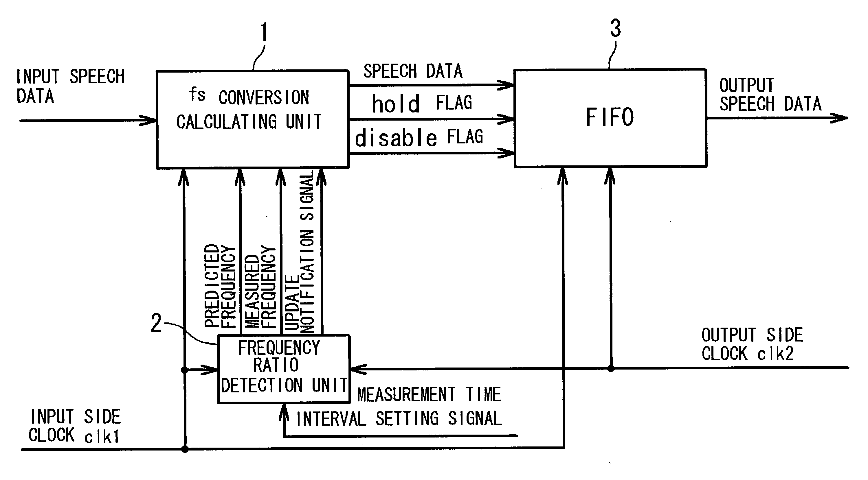
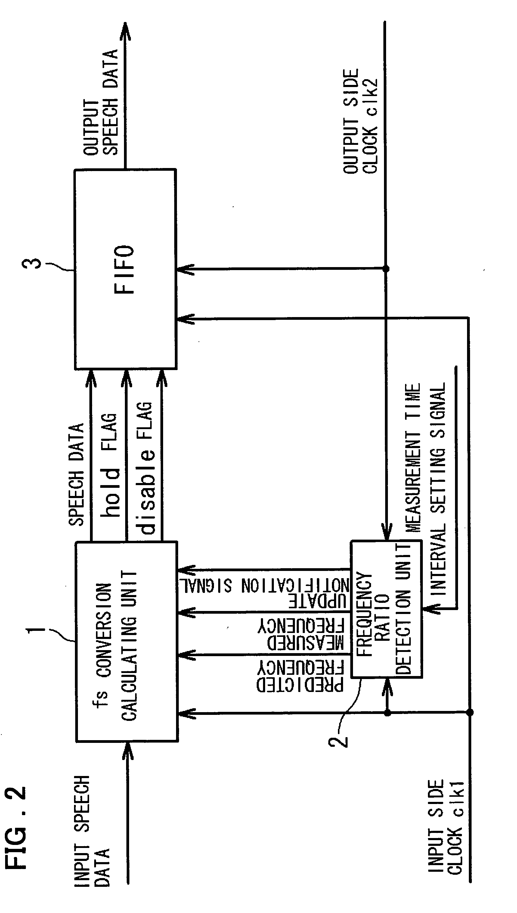
[0137]FIG. 2 is a block diagram showing the configuration of a sampling rate conversion apparatus in the best mode for carrying out the present invention. In the following explanation, a case of calculating the prediction frequency of an input side clock signal clk1 is taken as an example. However, in case the prediction frequency of an output side clock signal clk2 is calculated to effect sampling rate conversion, the sampling rate conversion of the present invention can be achieved by a similar sequence of operations. Referring to FIG. 2, the sampling rate conversion apparatus of the present embodiment is formed by an fs conversion calculating unit 1, a frequency detection unit 2 and by a FIFO 3.

[0138] The fs conversion calculating unit 1 is a calculating functional block for effecting calculation processing necessary for sampling rate conversion based on a prediction frequency, a...


PUM


Abstract

Disclosed is a sampling rate conversion apparatus for converting first data, sampled at a first sampling rate, into second data, sampled at a second sampling rate, includes a FIFO for storing the first data responsive to a first clock signal and for outputting the first data as second data responsive to the second clock signal. This FIFO stores the first data based on a write control signal indicating whether or not the first data written directly previously is to be updated to the first data, and outputs the second data read out based on a read control signal indicating whether or not the second data as read out is to be read out during the next time interval as well. The sampling rate conversion apparatus also includes a frequency detection unit for measuring the first clock signal during the current time interval to generate the value of the first current clock frequency, generating the value of a current predicted clock frequency from the value of the first current clock frequency and the value of the directly previously predicted clock frequency and for using the value of the current predicted clock frequency as the directly previously predicted clock frequency during the next time interval, and a calculating unit supplied with the first data to output the data to the FIFO. The calculating unit generates write control signal and read control signal from the value of a second current frequency, generated by measuring the second clock signal during the current time interval, and from the value of the current predicted clock frequency, to output the so generated write and read control signal to the FIFO.

Description

FIELD OF THE INVENTION [0001] This invention relates to a sampling rate conversion apparatus and, more particularly, to a method and an apparatus for converting the sampling rates between two sampling rates employing two clocks differing in both the frequency and the generating sources. BACKGROUND OF THE INVETNION [0002] There has so far been known a technique in which, when converting a speech data signal as an analog signal, into a digital signal, by way of AD conversion, the speech data signal is sampled a preset number of times per preset time to digitize the speech data signal. In the case of speech signal, the higher the sampling frequency, the higher may be the pitch of the sound that may be recorded, such that up to the frequency component corresponding to one-half the sampling rate can be completely restored to the original analog signal. [0003] Since the lower the sampling rate, the smaller may be the amount of data, there are occasions where, depending on the analog signa...

Claims


Application Information

Patent Timeline
Patent Type & Authority Applications(United States)
IPC IPC(8): H03H17/00H03H17/02H03H17/06H04B1/38H04B14/04
CPCH03H17/0628H03H17/0219
Inventor SUDO, EIJIOOI, YASUSHI
Owner RENESAS ELECTRONICS CORP
Why Eureka
Try Eureka