Power collection switching for automated driverless vehicles

a driverless vehicle and power collection technology, applied in the field of ground-based transportation systems, can solve problems such as arcing and other undesirable effects

Inactive Publication Date: 2007-06-05
HBB ASSETAB
View PDF4 Cites 11 Cited by
  • Summary
  • Abstract
  • Description
  • Claims
  • Application Information

AI Technical Summary

Problems solved by technology

Rapid change from a buss to a separating insulator and then to a successive buss as the vehicle moves forward results in arcing and other undesirable effects.

Method used


Image

  • Power collection switching for automated driverless vehicles
  • Power collection switching for automated driverless vehicles
  • Power collection switching for automated driverless vehicles

Examples


Embodiment Construction

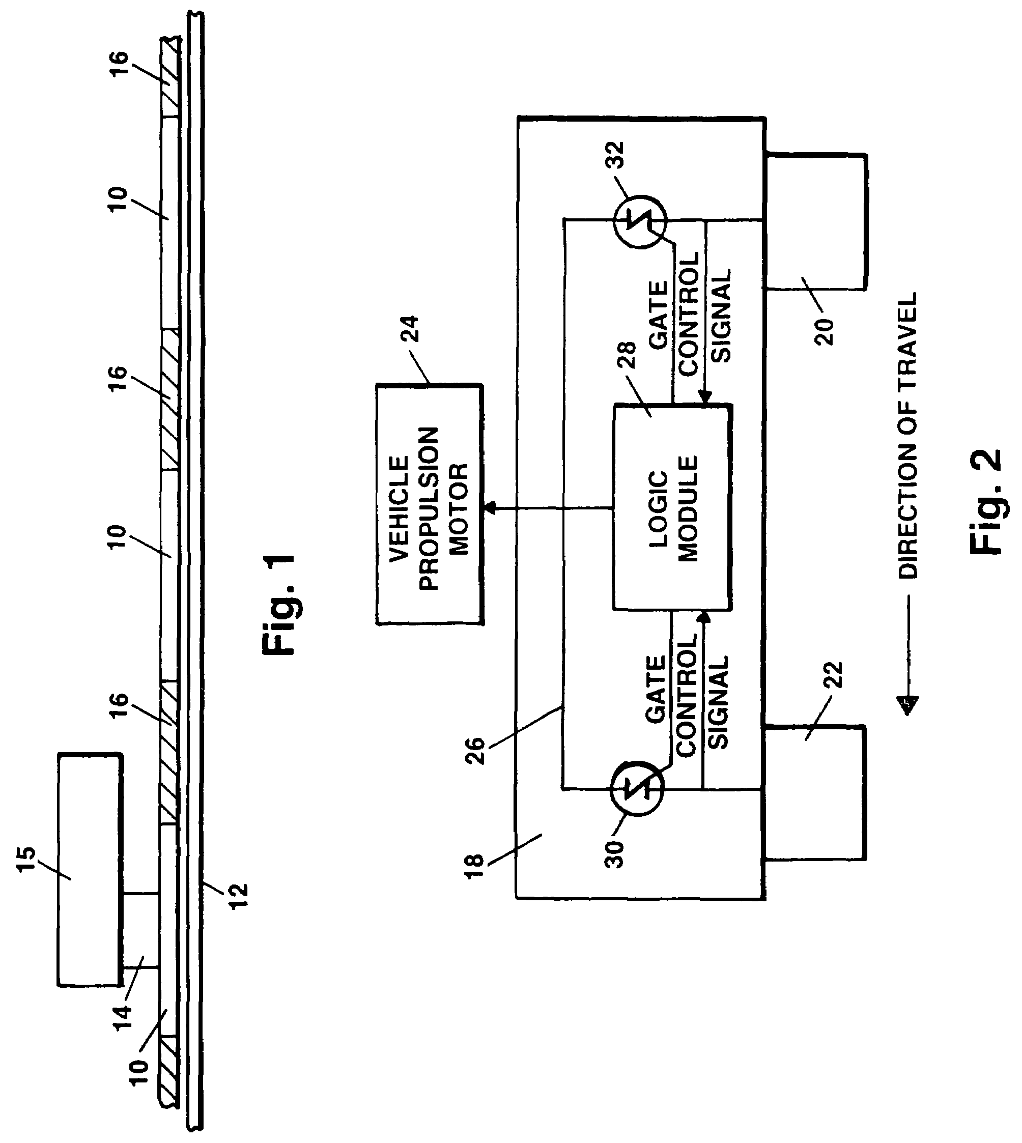
[0013]FIG. 1 depicts the single power collector arrangement disclosed in the prior art. The power collector may comprise, for example, a sliding brush or rotating element. As shown, the power collection sequence of the inventor's prior art patent U.S. Pat. No. 3,687,082 requires vehicle electrical propulsion power to be collected from power distribution segments 10 imbedded in or in close proximity to the vehicle guideway 12. Since the adjacent power distribution segments are powered by different power supplies it is essential that the vehicle power collector 14 does not short out two adjacent power segments as vehicle 15 travels along the guideway as this would cause the failure of the power supplies. It is therefore necessary that there be an insulator 16 positioned between each of the power segments 10, so that the brush or other type of power collector breaks connection with one power distribution segment 10 as it rides over an insulator 14 before it makes contact with the next ...


PUM


Abstract

Power switching apparatus for an electrically driven vehicle drawing power from a plurality of spaced apart ground disposed busses separated by insulators. The apparatus employs a pair of contacts for routing power from the busses to the vehicle motor, the speed of which is controlled by the power frequency presented at each successive buss as the vehicle proceeds on its journey. The contacts are serially positioned one after another with respect to the line of travel of the vehicle and are joined together by a switching mechanism which senses the power status of each contact at any particular moment. Power is transferred to the vehicle motor through one contact or the other in accordance with a selected sequence of operation. Voltage arcing and power lapse conditions are substantially alleviated by this arrangement.

Description

CROSS-REFERENCE TO RELATED APPLICATIONS[0001]This application is based on the disclosure of Provisional Application Ser. No. 60 / 676,515 filed May 2, 2005 by the same inventor which is hereby incorporated by reference.BACKGROUND OF THE INVENTION[0002]1. Field of the Invention[0003]The invention resides in the field of ground based transportation systems for passenger or freight and more particularly relates to apparatus for the programmable control of an electric vehicle.[0004]2. Description of the Prior Art[0005]This invention relates to an improvement in the transportation system concept disclosed in U.S. Pat. No. 3,687,082 by the same applicant. The method and apparatus employed in that system provide for vehicle speed control by the sequential application of multiple electrical power sources at varying frequencies to an electric motor used to power the vehicle.[0006]The vehicle receives power sequentially from a plurality of groups of busses connected to power supplies which gene...

Claims


Application Information

Patent Timeline
Patent Type & Authority Patents(United States)
IPC IPC(8): G05D1/00G08G1/00
CPCB60L5/42B60M1/36
Inventor BURKE, JR., HOWARD B.
Owner HBB ASSETAB
Why Eureka
Try Eureka