System and method for magnetization of permanent magnet rotors in electrical machines

a permanent magnet rotor and electric machine technology, applied in the field of electric machines, can solve the problems of cumbersome process of assembling the rotor from pre-magnetized permanent magnet segments, and process is prone to physical accidents

Active Publication Date: 2007-06-12
NUOVO PIGNONE TECH SRL
View PDF3 Cites 26 Cited by
  • Summary
  • Abstract
  • Description
  • Claims
  • Application Information

AI Technical Summary

Benefits of technology

[0007]Further aspects of the present technique provide an electrical machine manufactured in accordance with the above-described method.

Problems solved by technology

However, assembly of the rotor from pre-magnetized permanent magnet segments may be a cumbersome process, especially in larger electrical machines, as it may be time consuming and unwieldly.
The process is prone to physical accidents if energized permanent magnet blocks escape restraint.

Method used


Image

  • System and method for magnetization of permanent magnet rotors in electrical machines
  • System and method for magnetization of permanent magnet rotors in electrical machines
  • System and method for magnetization of permanent magnet rotors in electrical machines

Examples


Embodiment Construction

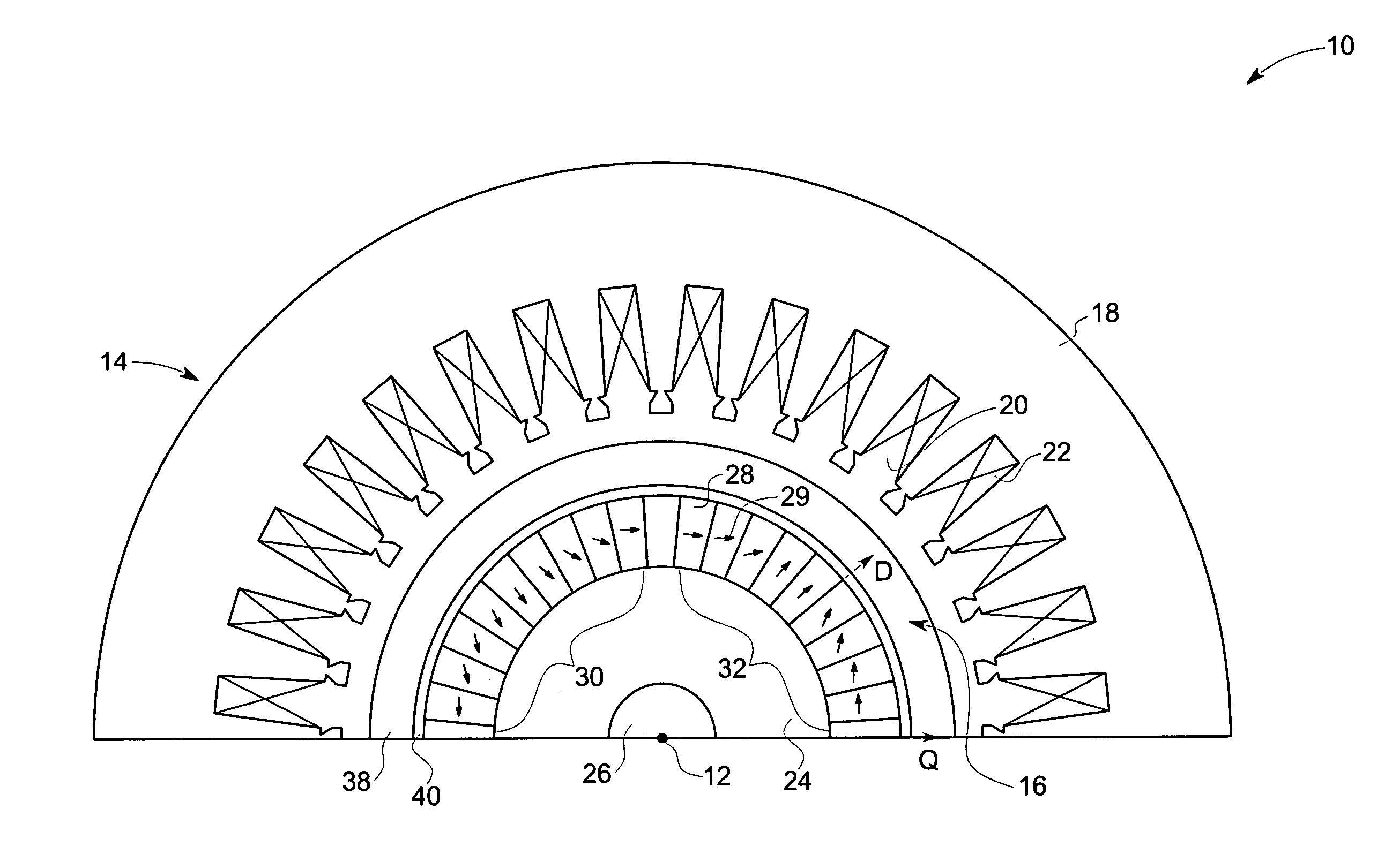
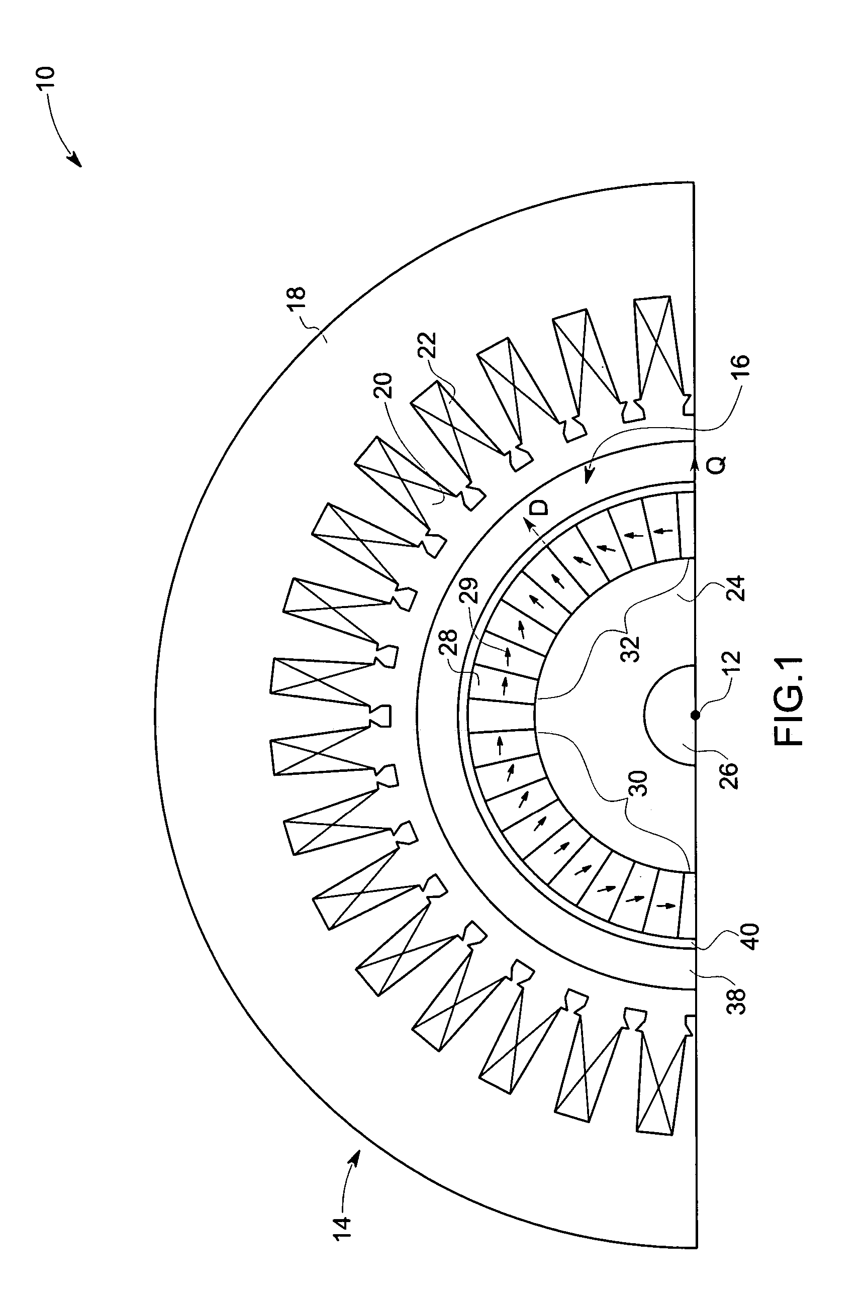
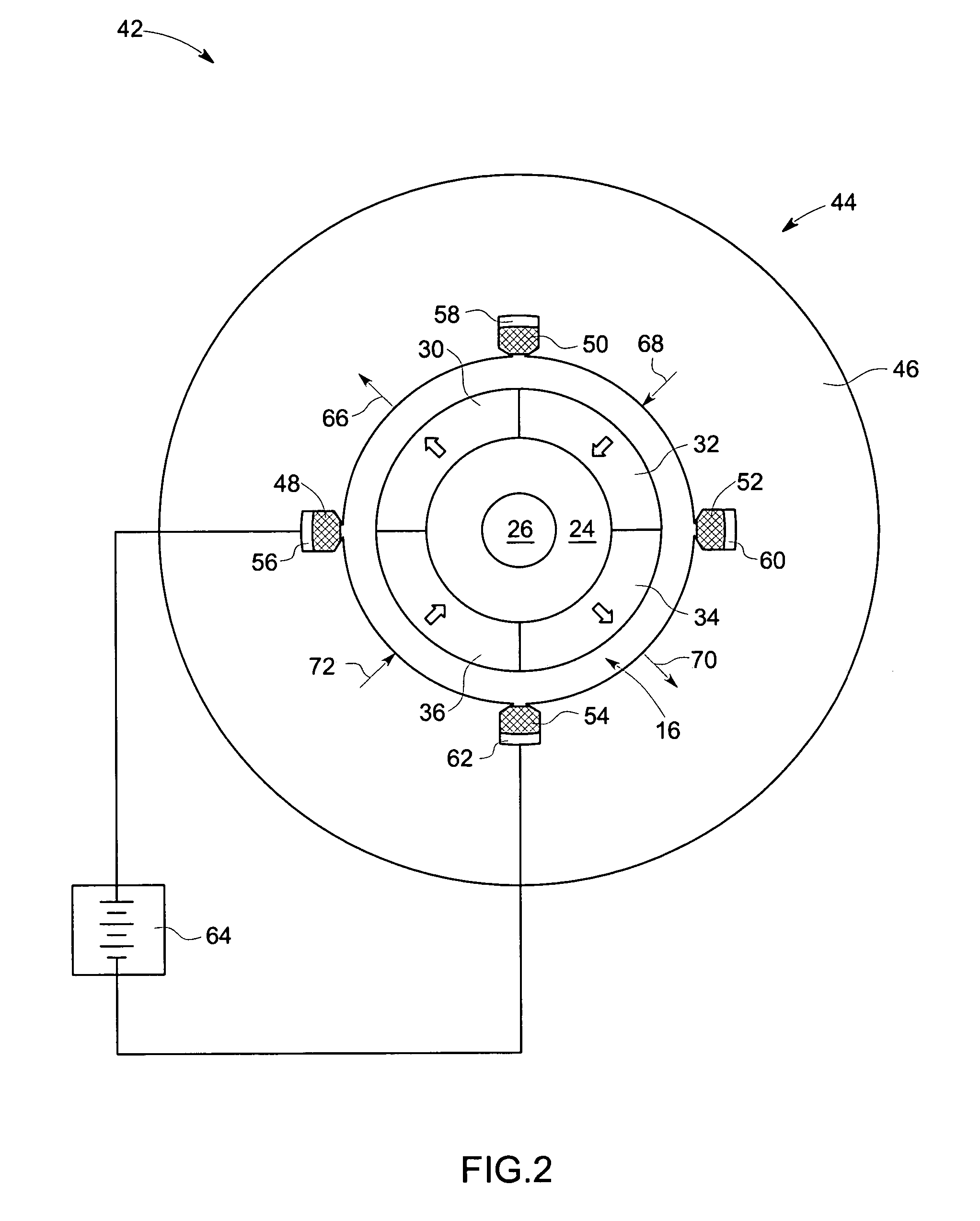
[0015]The present technique provides a system and method for magnetizing permanent magnet segments in an electrical machine rotor. In accordance with one aspect of the present technique, each pole of the rotor magnet comprises a Halbach array of permanent magnet segments. The present technique provides for a one-step magnetization of an entire assembled rotor in a multipole magnetizing fixture, in such a manner as to obtain optimal magnetization of the oriented magnets. Specific embodiments of the present technique are illustrated hereinafter with reference to FIGS. 1–6.

[0016]Referring now to FIG. 1, there is illustrated an exemplary portion of an electrical machine 10, wherein aspects of the present technique are incorporated. The electrical machine 10 may include, for example a polyphase synchronous electrical motor or generator. FIG. 1 shows a cross-sectional view taken in direction perpendicular to a rotary axis of 12 the electrical machine 10.

[0017]The electrical machine 10 com...


PUM

PropertyMeasurementUnit
magnetic analysisaaaaaaaaaa
magnetic fluxaaaaaaaaaa
magnetizationaaaaaaaaaa

Abstract

A system and method for manufacturing an electrical machine is provided. An array of permanent magnet segments is assembled around a rotor spindle. Desired orientation directions of the permanent magnet segments are determined. The assembled permanent magnet segments are then positioned in a magnetization fixture such that the desired orientation directions of the permanent magnet segments are aligned with corresponding flux directions of the magnetizing fixture.

Description

BACKGROUND[0001]The invention relates generally to electrical machines, particularly to electrical machines having permanent magnet type rotors. Specific embodiments of the present technique relate to a system and method for magnetization of permanent magnet segments in such rotors.[0002]An electrical machine, such as a motor or a generator, generally includes a rotor disposed within a stator and utilized to convert electrical power to mechanical power or vice versa. Certain electrical machines use permanent magnet type rotors, which reduce the size and enhance the overall efficiency of the machine. Such a rotor generally includes an annular permanent magnet, disposed over a rotor spindle. In certain embodiments, the permanent magnet is a monolithic, hollow, cylindrical member. In larger machines, the permanent magnet is generally formed by assembling a plurality of permanent magnets assembled around a rotor spindle. High speed electrical machines may also include a holding ring or ...

Claims


Application Information

Patent Timeline
Patent Type & Authority Patents(United States)
IPC IPC(8): H02K1/28H01F13/00H02K21/12
CPCH02K1/278H02K15/03Y10T29/49012
Inventor STEPHENS, CHARLES MICHAEL
Owner NUOVO PIGNONE TECH SRL
Why Eureka
Try Eureka