Guide assembly for guide rail comprising pair of angled guide wheels

a technology of guide rails and guide rails, which is applied in the direction of steering controls, non-vehicle mounted steering controls, locomotives, etc., can solve the problems that the guide wheels and/or the guide assembly arm cannot be eliminated, and achieve the effect of less wear on the guide wheel

Active Publication Date: 2007-06-12
LOHR IND
View PDF7 Cites 40 Cited by
  • Summary
  • Abstract
  • Description
  • Claims
  • Application Information

AI Technical Summary

Benefits of technology

[0013]Preventing contact between the covering on the guide wheel and the rail when lateral force is exerted keeps the covering from deteriorating prematurely and ensures that there is less wear on it.

Problems solved by technology

However, exceptional force on the guide wheels and / or the arm of the guide assembly cannot be eliminated.

Method used


Image

  • Guide assembly for guide rail comprising pair of angled guide wheels
  • Guide assembly for guide rail comprising pair of angled guide wheels
  • Guide assembly for guide rail comprising pair of angled guide wheels

Examples


Embodiment Construction

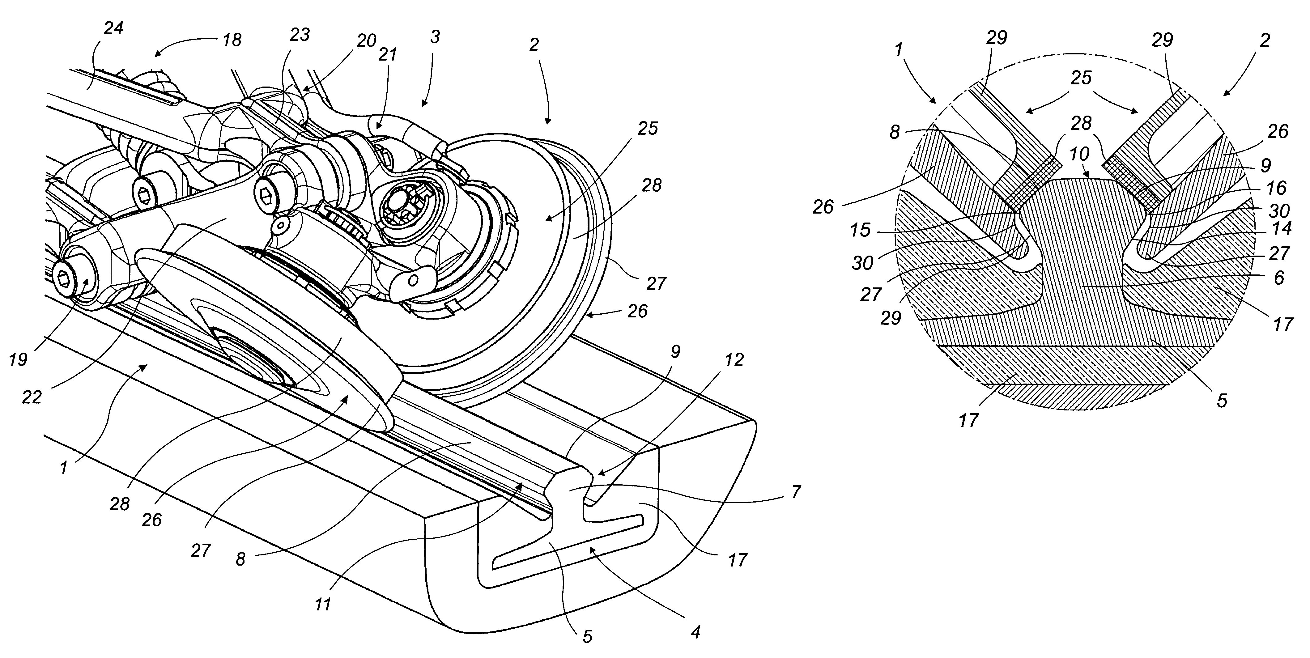
[0019]The invention relates to an angled guide wheel 1 or 2, as well as a pair 1 and 2 of angled guide wheels forming a guide assembly, and to a guide rail adapted to said guide wheels.

[0020]As shown, these guide wheels are used in pairs angled at a V in a guide assembly 3 to travel along a guide rail 4 adapted to them.

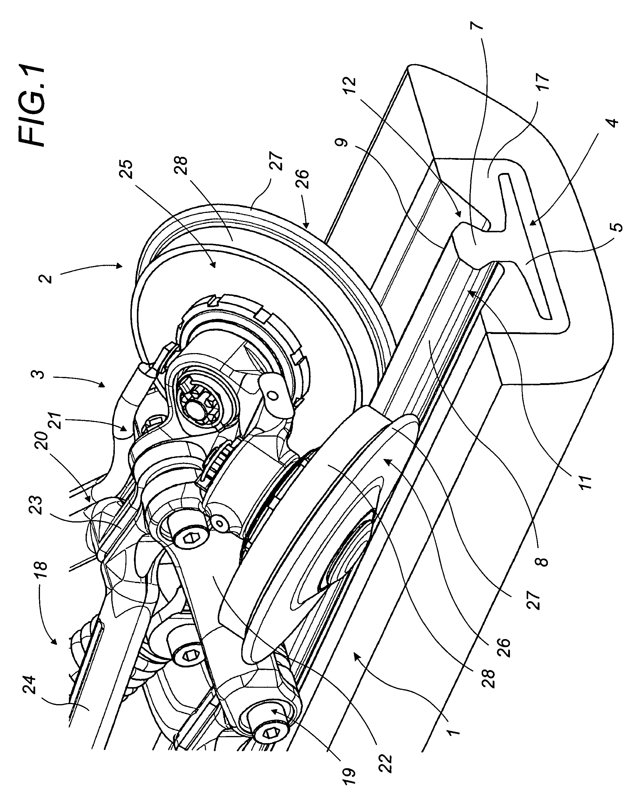
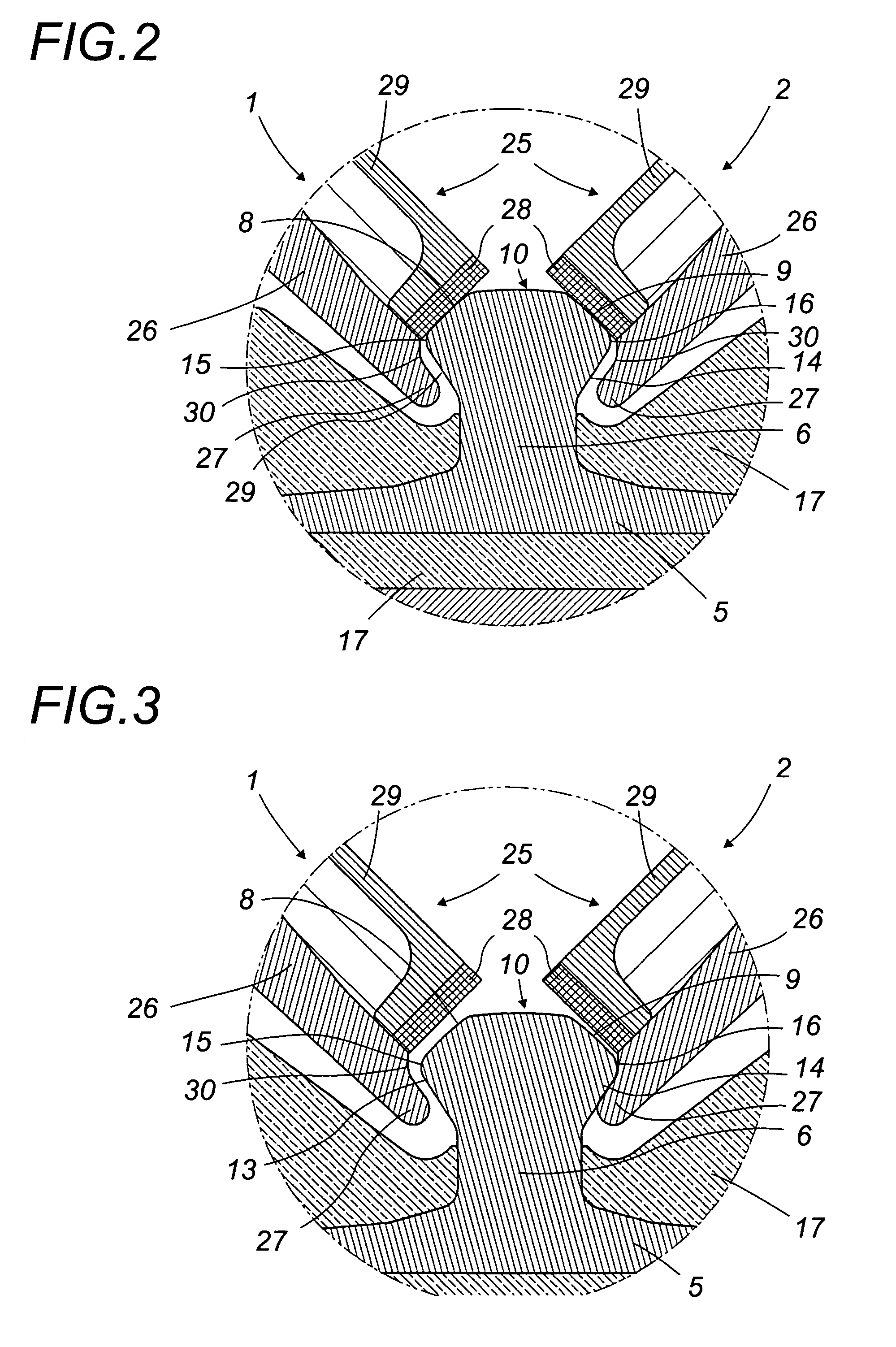
[0021]This guide rail 4 has a bed 5, a core 6 and a rail head 7. On the latter portion there are two plane or slightly concave inclined travel pathways 8 or 9 along each of which a guide wheel 1 or 2 moves, respectively. The guide rail also has an upper table 10 and on either side, a projection 11 and 12 each formed of an inclined ramp 13 or 14, each extending into one of the corresponding travel pathways 8 or 9 following transitional rounded edge 15 and 16.

[0022]As indicated, the succession of travel pathway, rounded edge and corresponding inclined ramp each form one of the projecting sides 11 and 12 of guide rail 4. These projecting sides are the general characteris...


PUM


Abstract

The flanged type guide wheel (1) or (2) has a peripheral edge (27) which has within its profile a recess (30), for example, a notch, the shape and position of which maintain the surface cover (28) of the guide wheel at a distance from the travel surface (8) or (9) that exists opposite it on the guide rail (4) when there is lateral force on the guide wheel. This invention has applications for guide assemblies for road vehicles used on guide rails.

Description

[0001]This application claims Priority from French Patent Application Serial No. 0401236 filed Feb. 9, 2004.FIELD OF THE INVENTION[0002]The invention relates to an angled guide wheel designed for a guide assembly with two identical guide wheels angled at a “V” moving along a guide rail.BACKGROUND OF THE INVENTION[0003]It is important that the guide assembly on a road vehicle that uses guide wheels to travel along a guide rail be stable, move without vibrating, and be as quiet as possible[0004]Wear and tear on the wheels must be controlled, with wheels being changed as seldom as possible, ideally, during periodic technical checkups.[0005]In addition, primarily for safety reasons, the design of the guide assembly and the shape of the wheels and guide rail must serve to minimize any tendency to derailment and they should be designed to reduce and preferably compensate for any force which, if amplified, would lead to derailment.[0006]Replacing worn out parts in the guide assembly should...

Claims


Application Information

Patent Timeline
Patent Type & Authority Patents(United States)
IPC IPC(8): B61B12/02B61C11/00B61F9/00B62D1/26E01B25/28
CPCB61F9/00B62D1/265E01B25/28
Inventor ANDRE, JEAN-LUCMAUPU, JEAN-LOUISGANTER, DIDIER
Owner LOHR IND
Why Eureka
Try Eureka