

Radio and optical identification tags
a radio and optical identification technology, applied in the field of identification tags, can solve the problems of reader collision, tag cost increase, and tag collision
- Summary
- Abstract
- Description
- Claims
- Application Information
AI Technical Summary
Benefits of technology
Problems solved by technology
Method used
Image

Examples
Embodiment Construction
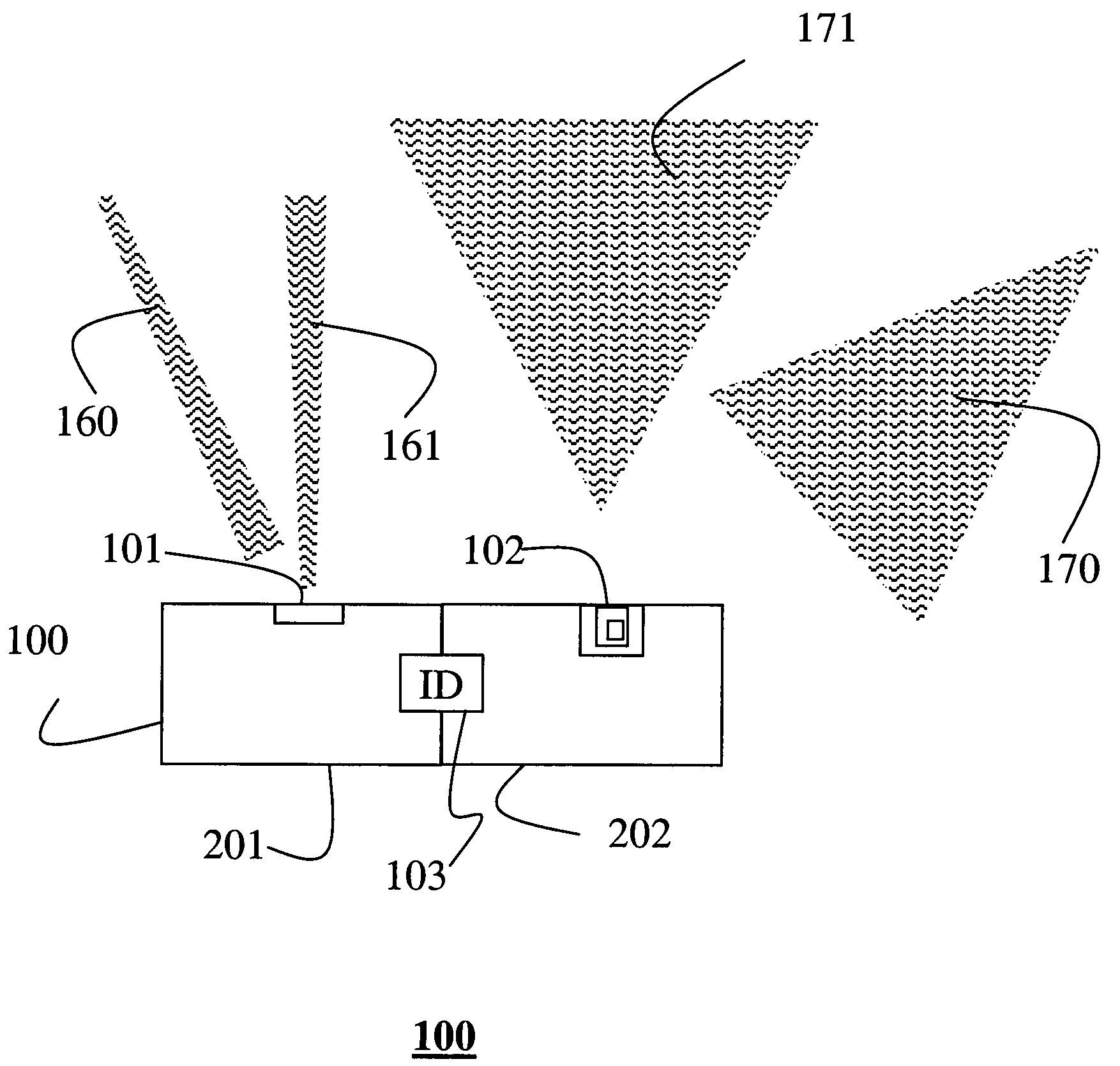
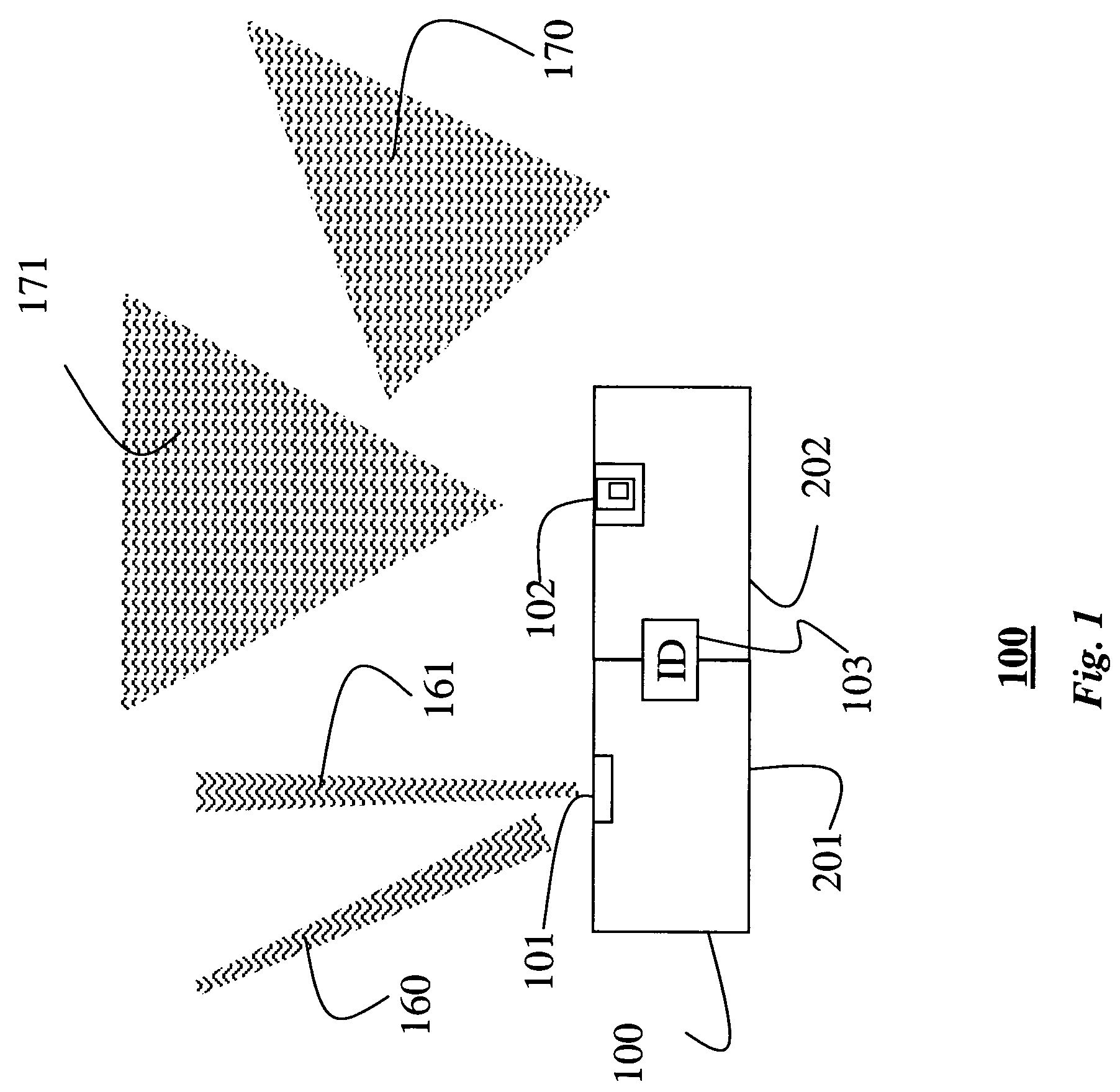
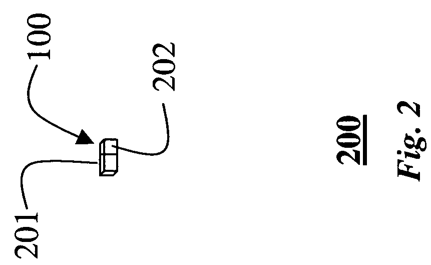
[0016]FIGS. 1 and 2 show an identification tag 100 according to the invention. The tag is formed on a single integrated microcircuit, e.g. a coupled of millimeters on each side. The tag is comparable to RFID tags as known in the art. The primary purpose of the tag is to provide identification to users. In addition, the tag according to the invention also provides for visual identification.
[0017]The tag 100 includes an optical-frequency (OF) transceiver 201 and a radio-frequency (RF) transceiver 202. The OF transceiver uses a single frequency band (optical channel) to receive and transmit signals. The RF transceiver uses another single frequency band (RF channel) to transmit and receive signals.
[0018]The OF transceiver201 includes a photodiode or phototransistor 101 that is capable of receiving light 160 and transmitting light 161 in a specific frequency band. U.S. patent application Ser. No. 10 / 126,761 “Communication Using Bi-Directional LEDs,” filed by Dietz et al. on Apr. 19, 2002...
PUM
 Abstract
Description
Claims
Application Information