Shackle assembly

a technology of shackle and shackle plate, which is applied in the direction of spring/damper, mechanical apparatus, transportation and packaging, etc., can solve the problems of inability to provide sufficient lateral and conical stiffness of the suspension, inability to provide vertical compliance of the conventional assembly, and inability to use rigid, rigid, heavy bushings and shackle plates. to achieve the effect of enhancing vertical, torsional and conical performance, and enhancing suspension travel

Inactive Publication Date: 2007-06-12
HENDRICKSON USA L L C
View PDF22 Cites 60 Cited by
  • Summary
  • Abstract
  • Description
  • Claims
  • Application Information

AI Technical Summary

Benefits of technology

[0016]The present invention relates to a unique shackle assembly. In its preferred form, the shackle assembly includes elastomer bushings to enhance suspension travel without inducing compressive stress to the associated leaf spring. The shackle assembly also preferably includes built-in redundancy features. The shackle assembly comprises a shackle bracket secured between two wear pads and two shackle plates, and a bushing incorporated therein. The shackle bracket includes downwardly extending legs, which serve as contact surfaces for the wear pads and shackle plates and, thereby provide lateral and conical stiffness. These shackle bracket legs allow for the use of a more versatile, elastomer bushing having voids oriented to enhance vertical, torsional and conical performance. The elastomer bushing is preferably in the form of a bowtie-shaped bushing. A first redundancy feature is in the form of a laterally extending shackle stop secured between the shackle plates at one side thereof. The shackle stop, which is preferably in the form of a tube, provides longitudinal control of the axle in the event the opposite limb of the leaf spring breaks, the vehicle is moving in a first direction and the vehicle is subjected to deceleration. In that regard, and under those circumstances, the shackle stop will contact the shackle bracket legs. A second redundancy feature is in the form of fingers forming a portion of the shackle plates positioned on the same side of the shackle plates as the shackle stop. The fingers preferably extend vertically upwardly and contact the bottom of the adjacent frame rail in the event the opposite limb of the leaf spring breaks, the vehicle is moving in a second direction generally opposite the first direction, and is subject to deceleration.

Problems solved by technology

One recognized problem of conventional shackle assemblies is their ineffectiveness in providing sufficient suspension lateral and conical stiffness, primarily due to the large distance spanned between the shackle plates.
Those skilled in the art will recognize that conventional shackle assemblies require strong, stiff, heavy, and, therefore, costly bushings and shackle plates.
Those skilled in the art will further recognize that the non-rubber (i.e., strictly metal) bushings used in conventional assemblies are unable to provide vertical compliance.
Accordingly, conventional shackle assemblies could undesirably induce compressive stress in the leaf spring.
Another item not present in the prior art is that conventional shackle assemblies typically do not incorporate built-in redundancy features to help provide vehicle control in the event of a broken spring.
Suspensions utilizing conventional shackle assemblies traditionally require an additional leaf with “military wrap.” Those skilled in the art will recognize that these and similar redundancy features add cost, weight, and complexity to the suspension.

Method used


Image

  • Shackle assembly
  • Shackle assembly
  • Shackle assembly

Examples


Embodiment Construction

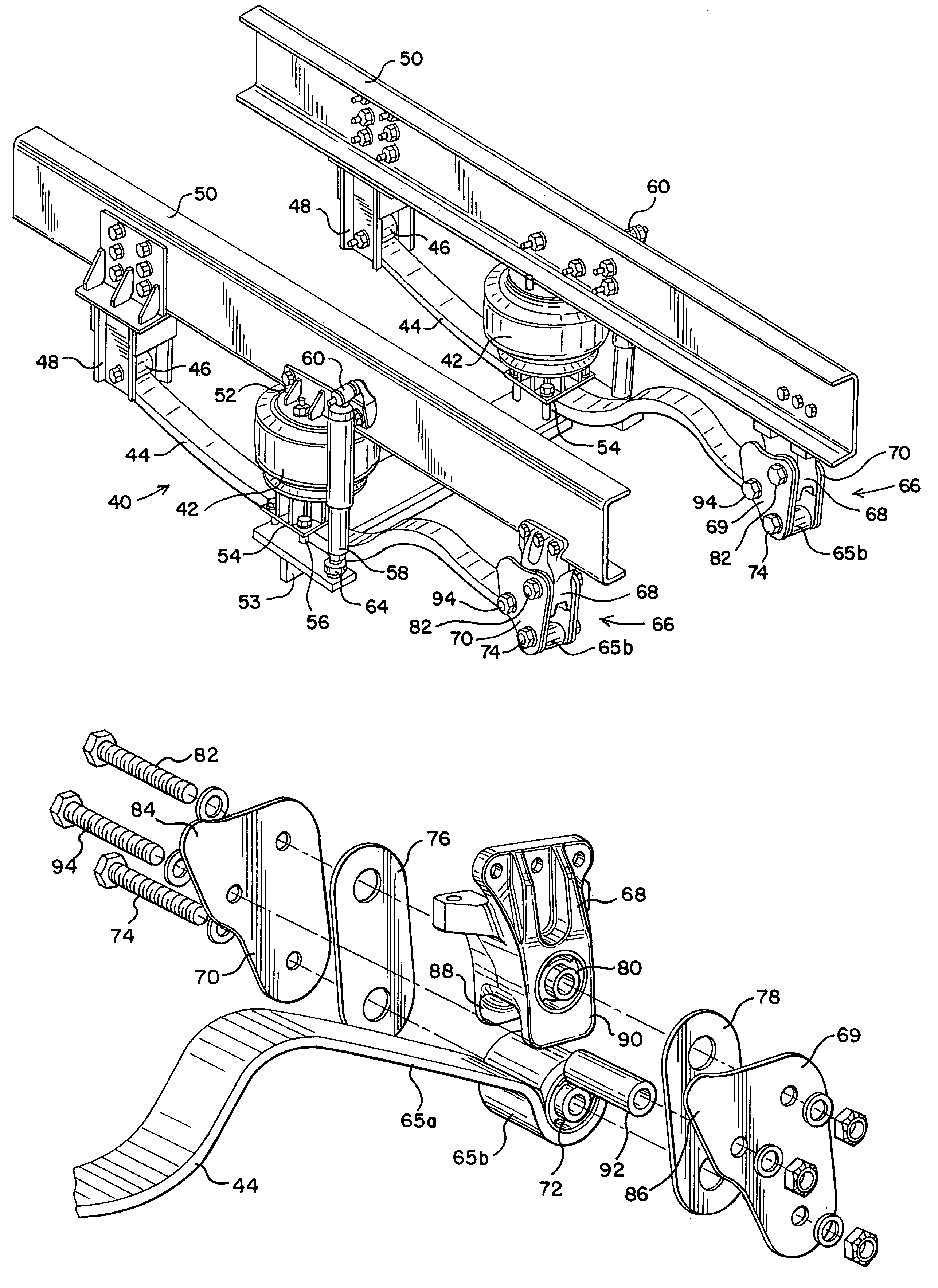
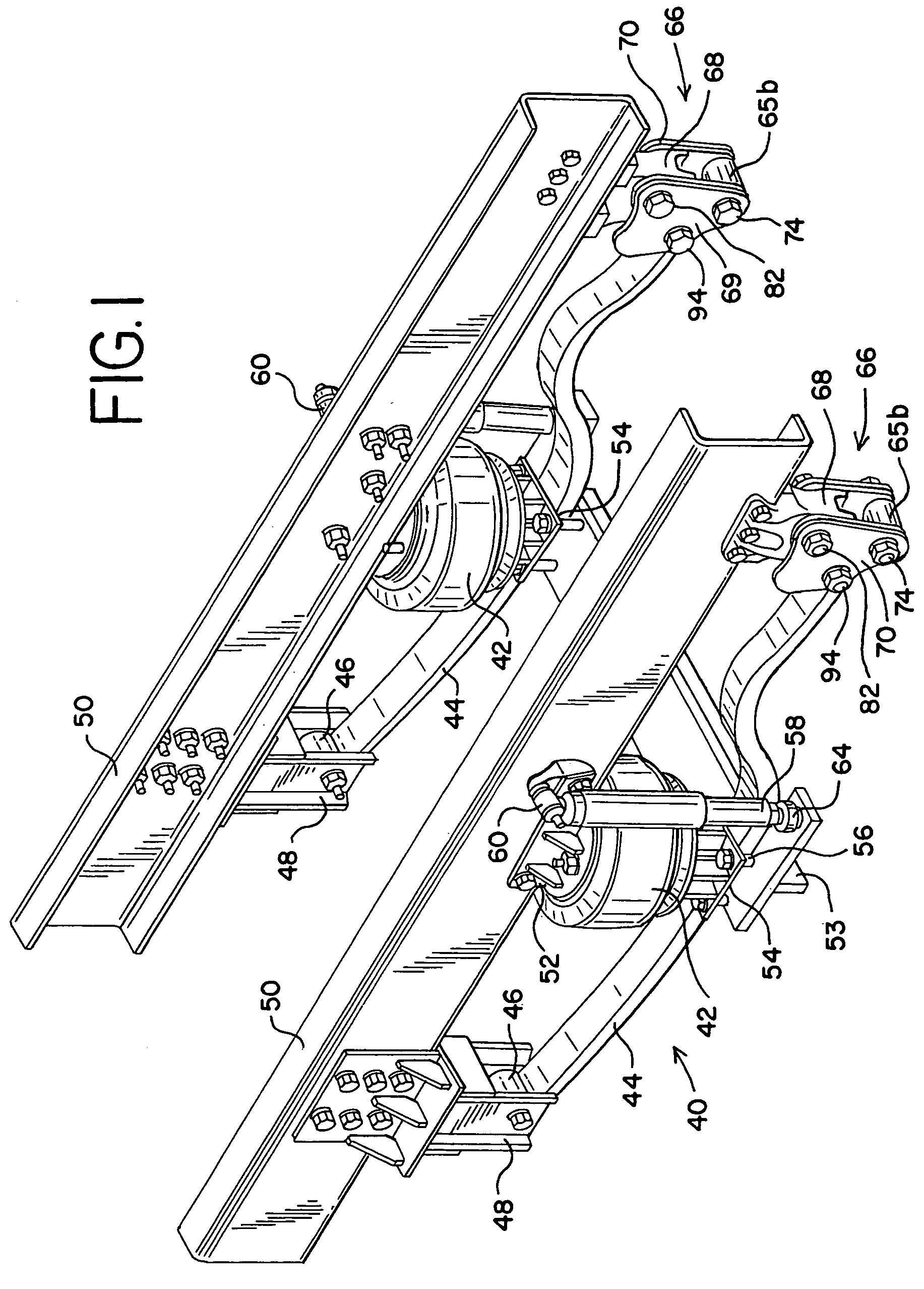
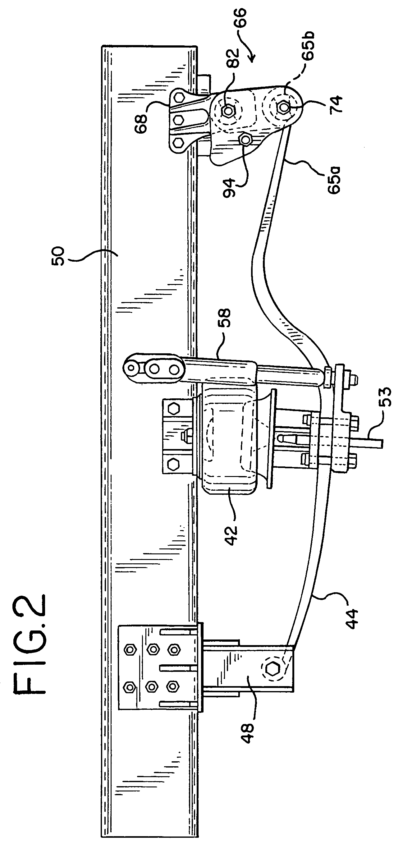
[0023]FIGS. 1–2 illustrate a steering axle / front suspension system generally designated by reference number 40. It will be seen and understood that the construction of this suspension system on one side is duplicated on the opposite side of the vehicle. It will further be understood that, although the shackle assembly forming the subject matter of the present invention is shown as being positioned at the rear end of a leaf spring included with the suspension system, it could have equal utility at the opposite end of the leaf spring.

[0024]Furthermore, while the illustrated embodiment is directed to a combination air-mechanical suspension, it will be understood by those skilled in the art that the present invention has utility in strictly mechanical suspensions as well. Still further, the present invention is not limited to single-leaf leaf spring suspensions, and is not limited to front suspensions, as illustrated.

[0025]The active or functional components of the front suspension syst...


PUM

PropertyMeasurementUnit
forceaaaaaaaaaa
stiffnessaaaaaaaaaa
contact surfaceaaaaaaaaaa

Abstract

A shackle assembly is shown to include a shackle bracket, wear pads, a shackle stop, shackle plates and elastomer bushings. The shackle bracket includes legs forming portions thereof, which serve as contact surfaces for the wear pads and the shackle plates. By providing conical and lateral stiffness, the shackle bracket legs allow for the use of a more versatile elastomer bushing. The elastomer bushing preferably includes voids vertically separated with respect to each other and the elastomer layer preferably is in the form of a bowtie-shaped configuration, which enhances vertical, conical and torsional performance. A first redundancy feature is in the form of a shackle stop secured between the shackle plates. The shackle stop provides longitudinal control of the axle in the event the opposite limb of the leaf spring is broken, the vehicle is generally traveling in a given direction and the vehicle is subject to deceleration. A second redundancy feature is in the form of fingers forming portions of the shackle plates, which provides longitudinal control of the axle under the same conditions, but when the vehicle is generally traveling in an opposite direction. The redundancy features are activated under other conditions as well.

Description

[0001]This is a continuation of application Ser. No. 10 / 280,120, filed on Oct. 24, 2002, now abandoned.BACKGROUND OF THE INVENTION[0002]The present invention relates generally to vehicle components, and more particularly, to shackle assemblies used to connect vehicle suspension components to a vehicle frame.[0003]Shackle assemblies are typically used in a variety of vehicle suspensions to connect vehicle suspension components to a vehicle frame. Conventional shackle assemblies are typically used in leaf spring front suspensions, but typically do not use elastomer bushings. In a conventional shackle assembly, the suspension side loads are carried through the conical loading of the non-rubber bushings through the shackle plates. These shackle assemblies primarily rely on the bushing properties and shackle plate stiffness to provide for suspension lateral and conical stiffness.[0004]One recognized problem of conventional shackle assemblies is their ineffectiveness in providing sufficie...

Claims


Application Information

Patent Timeline
Patent Type & Authority Patents(United States)
IPC IPC(8): B60G1/00B60G7/04B60G11/12B60G11/46B60G17/02F16F1/368
CPCB60G7/04B60G11/12B60G11/465B60G17/023F16F1/368B60G2200/31B60G2202/112B60G2202/152B60G2204/121B60G2204/126B60G2204/129B60G2204/4104B60G2204/43B60G2204/4302B60G2204/45B60G2206/428B60G2206/601B60G2206/91B60G11/04B60G11/10
Inventor DUDDING, ASHLEY THOMASASTUDILLO, GONZALO LUNACORTEZ, JEROME LIM
Owner HENDRICKSON USA L L C
Why Eureka
Try Eureka