Soil compacting device comprising an undercarriage

a technology of soil compacting and undercarriage, which is applied in the direction of soil preservation, roads, roads, etc., can solve the problems of user injury risk, high construction cost of the pivot mechanism, and poor travel behavior, so as to reduce the risk of user injury, reduce the cost of purchasing, and reduce the time of failure

Inactive Publication Date: 2007-12-04
WACKER NEUSON SE
View PDF8 Cites 10 Cited by
  • Summary
  • Abstract
  • Description
  • Claims
  • Application Information

AI Technical Summary

Benefits of technology

[0014]In comparison with conventional devices, the fact that the undercarriage axle is stationary with respect to the device means that the roller elements are already in their travel position during vibration operation. In this way, an extending or pivoting of the undercarriage axle is not required for transport, and a part of the mechanism that is particularly susceptible to wear, namely the extension or pivoting mechanism, is omitted, resulting in

Problems solved by technology

However, the pivot mechanism has an expensive construction, in order to avoid wear on the pivot bearings due to the vibrations that occur.
Due to the situation of the drawbar and a very large distance of the center of gravity of the overall system from the rotational axle of the wheels, the

Method used


Image

  • Soil compacting device comprising an undercarriage
  • Soil compacting device comprising an undercarriage
  • Soil compacting device comprising an undercarriage

Examples


Embodiment Construction

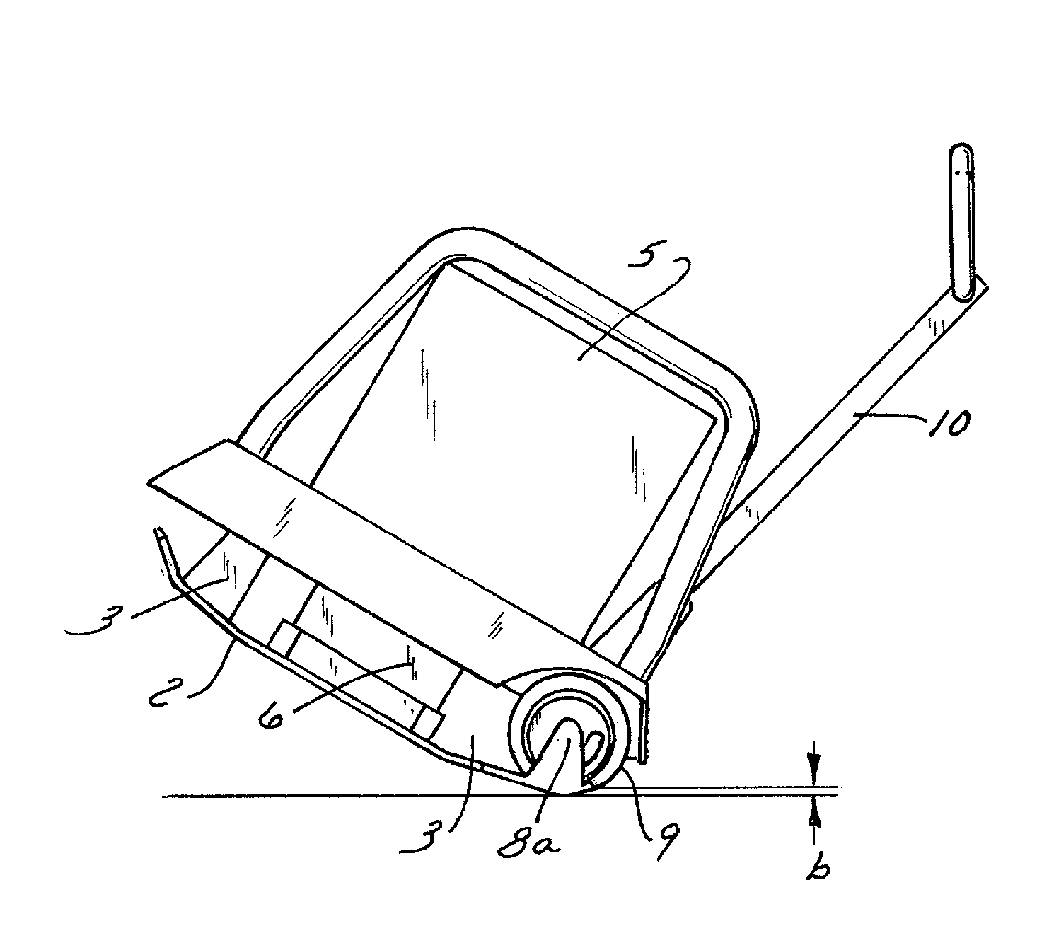
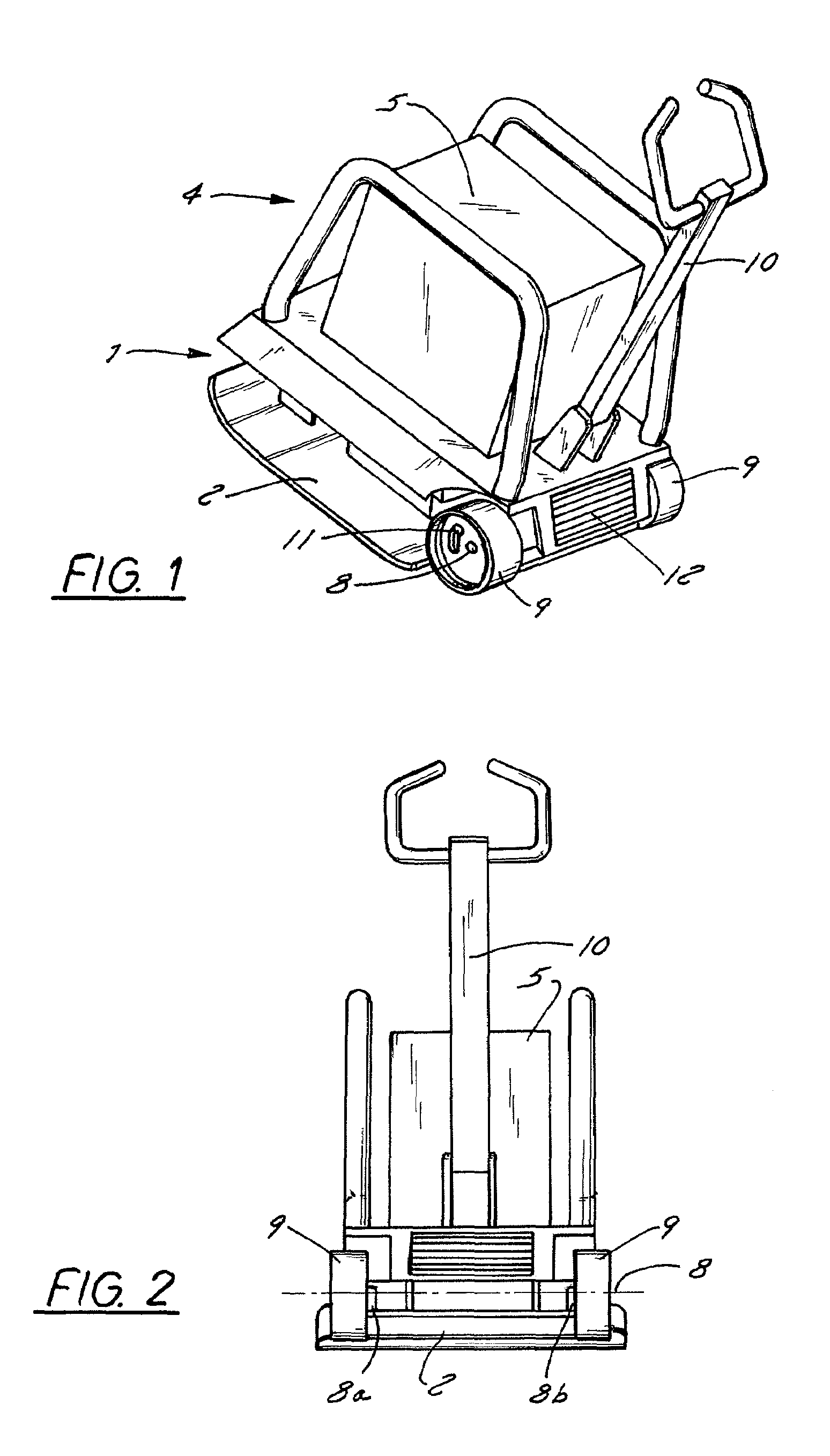
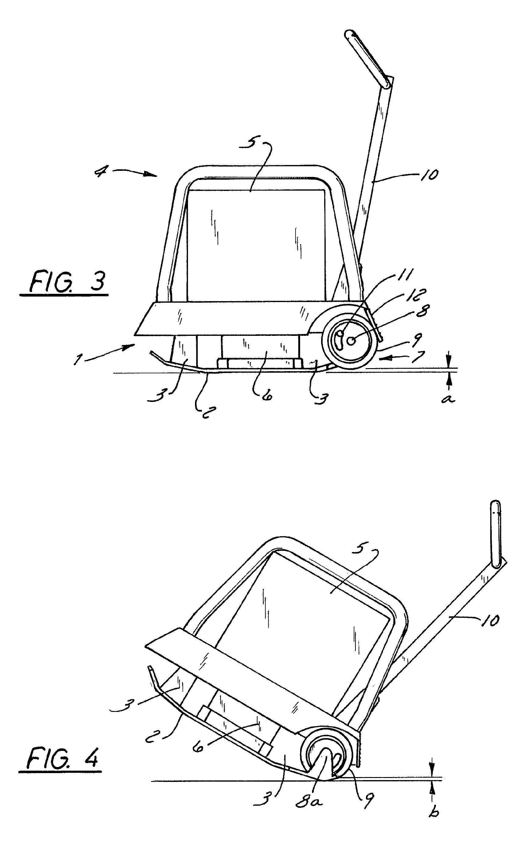
[0024]A drive unit associated with an upper mass 4 and hidden under a covering 5 is positioned on a compacting plate 2 associated with a lower mass 1, coupled via a spring damping device 3.

[0025]The drive, which is standardly a gasoline or diesel engine, drives a vibration generator 6 that is coupled with compacting plate 2 in such a way that the vibrations produced by vibration generator 6 are transmitted directly to compacting plate 2, and thus into the soil to be compacted.

[0026]Undercarriage 7 comprises an undercarriage axle 8 that is stationary in relation to the soil compacting device, about which one or more roller elements 9 are situated so as to be capable of rotation. In the embodiment shown here, which is particularly advantageous, undercarriage 7 is attached to lower mass 1, in particular to compacting plate 2. This reduces the distance of the center of gravity of the overall device from undercarriage axle 8, resulting in an improvement of the travel behavior of the devi...


PUM


Abstract

The invention relates to a soil compacting device, especially a vibrating plate, which comprises an undercarriage mounted on a lower body, said undercarriage having an undercarriage axle that is stationary with respect to the device. By suitably positioning the undercarriage axle it is achieved that, in a vibrating position, the rolling bodies do not touch ground while they do touch ground when the entire device is simply tilted about an axis that corresponds approximately to the undercarriage axle, thereby allowing the mobility of the device. The soil compacting device is advantageous over conventional devices in that an extension or swiveling of the undercarriage axle for the purpose of transport and the corresponding devices are no longer required.

Description

BACKGROUND OF THE INVENTION[0001]1. Field of the Invention[0002]The present invention relates to a soil compacting device according to the preamble of patent claim 1.[0003]2. Description of the Related Art[0004]Such a soil compacting device is for example a vibration plate in which a vibration generator, driven by a motor, produces an essentially vertically oriented vibration that loads a compacting plate. Depending on the design of the vibration generator, this generator is also suitable for moving the compacting plate forwards or backwards over the soil to be compacted, and for making the plate steerable.[0005]Such a soil compacting device is known for example from DE 198 40 453 A1. It comprises an extendable undercarriage, so that the device can travel shorter distances on a construction site without requiring a transport vehicle.[0006]In CH-A-321022, a vibration plate is described in which there is attached to the upper mass a pivot mechanism by which an undercarriage can be piv...

Claims


Application Information

Patent Timeline
IPC IPC(8): E01C19/34E01C19/38E02D3/046
CPCE02D3/046
Inventor SCHENNACH, HERMANNKUCHLER, MARCUS
Owner WACKER NEUSON SE
Why Eureka
Try Eureka