Keypad in textiles with capacitive read-out circuit

a capacitive read-out circuit and keypad technology, applied in the field of input devices, can solve problems such as failure, and achieve the effect of increasing the detection distance and the speed at which the object approaches the key devi

Active Publication Date: 2007-06-12
FUTURE SHAPE
View PDF10 Cites 96 Cited by
  • Summary
  • Abstract
  • Description
  • Claims
  • Application Information

AI Technical Summary

Benefits of technology

[0017]In accordance with a preferred embodiment, the conductors electrically connected to the key devices in each case are electrically connected at crossover points to contact redistribution conductors which run essentially perpendicularly thereto and in each case comprise at least one electrically conductive weft or warp thread of the fabric carrier. This “contact redistribution” of the conductors, serving as signal lines for the key devices, to contact redistribution conductors running essentially perpendicularly thereto enables the conductors, which are often spaced apart from one another comparatively far and irregularly, to be diverted to closely adjacent and regularly arranged contact redistribution conductors. The large distance between the conductors which is often necessary in order to form a textile “keyboard” can thus be adapted to the contact or conductor period of electronic components, which is typically an order of magnitude smaller. In this case, the evaluation device is connected to the contact redistribution conductor. If, by way of example, electrically conductive warp threads of the textile fabric carrier are used as conductors, then the contact redistribution conductors may be formed by weft threads having crossover points with said warp threads.
[0033]Preferably, the key device is fitted by means of a printing method, in particular a screen printing method. This enables the simple production—accessible to mass production—of key devices which are fixed to the textile fabric carrier such that they are well embedded in the textile environment. Preferably, an electrical insulation of the conductor is locally removed before the step of fitting the key device.

Problems solved by technology

Furthermore, a conductor formed in this way also does not represent an extraneous element in the textile environment, as is the case with conventional key devices fitted on textile fabric carriers.

Method used


Image

  • Keypad in textiles with capacitive read-out circuit
  • Keypad in textiles with capacitive read-out circuit
  • Keypad in textiles with capacitive read-out circuit

Examples


Embodiment Construction

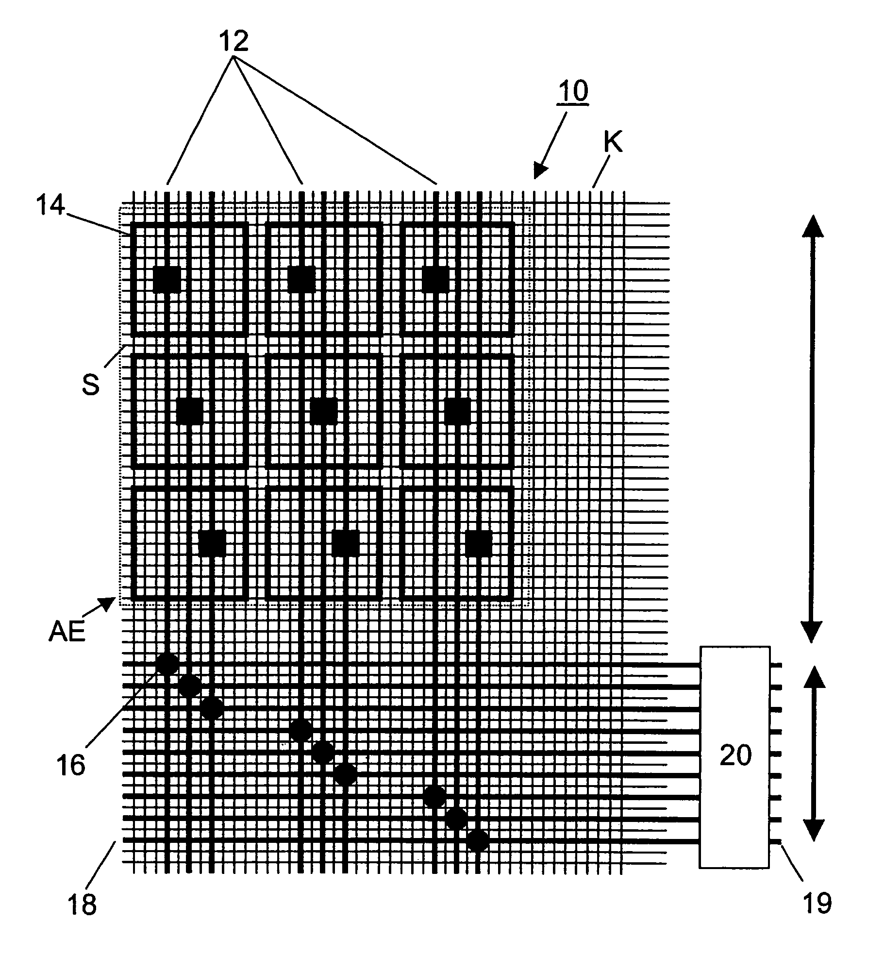
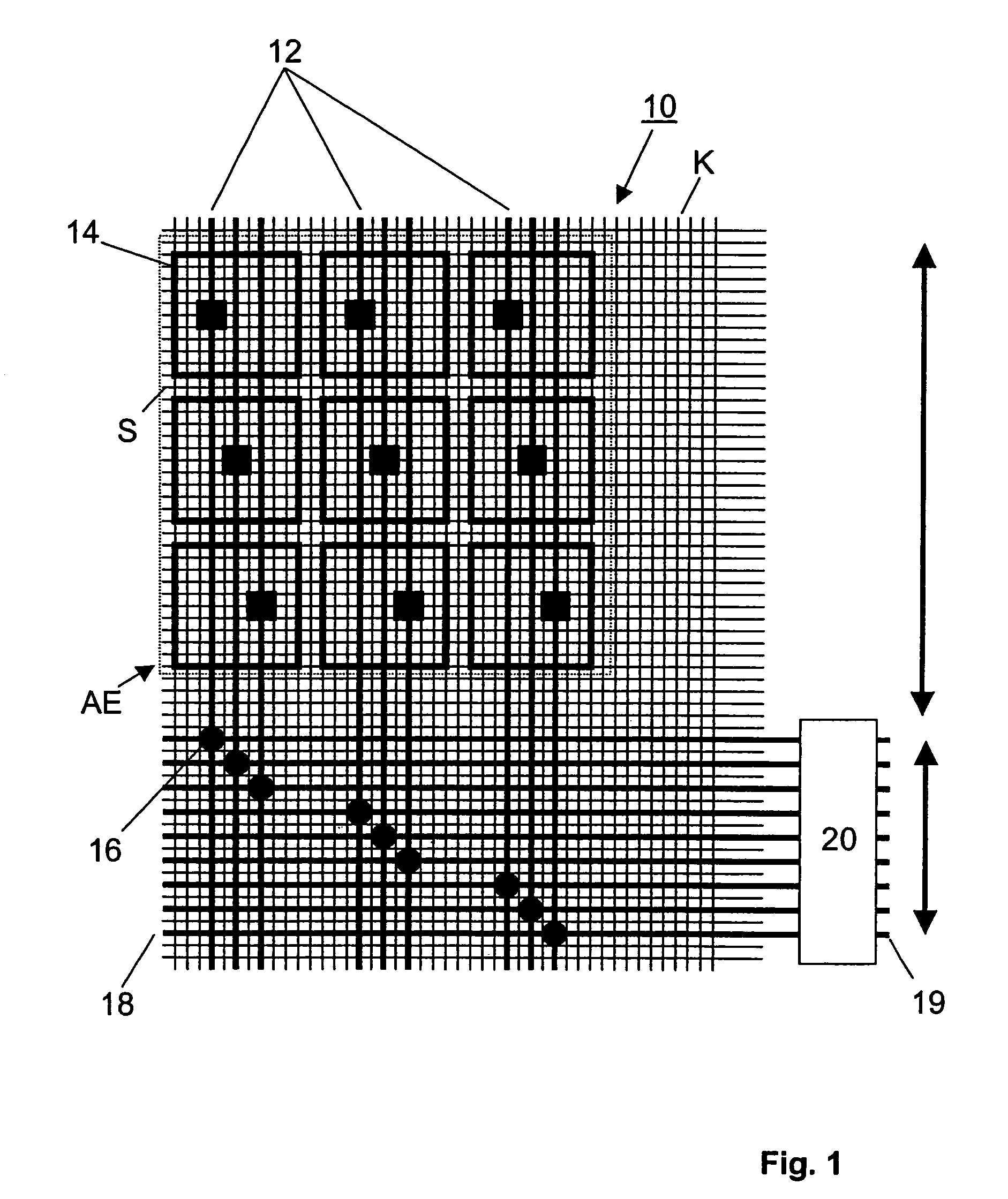
[0040]FIG. 1 illustrates a first preferred embodiment of an input apparatus according to the invention. 10 designates a textile fabric carrier having a multiplicity of warp threads K and weft threads S. The warp and weft threads K, S preferably for the most part comprise electrically insulating synthetic fibers and are thus insulators. Some selected synthetic fibers thereof have spun-in thin metal wires, however, which are electrically insulated. Electrical conductivity is thereby imparted to these selected warp and weft threads, so that they represent wire- and / or thread-like electrical conductors 12. The electrically conductive warp and weft threads K, S, which in each case form a conductor 12 in the embodiment shown in FIG. 1, are highlighted by a thicker line width in FIG. 1. It is also possible for a plurality of—in particular adjacent—electrically conductive warp and weft threads to be interconnected to form an electrical conductor 12, for redundancy reasons.

[0041]Key devices ...


PUM

PropertyMeasurementUnit
flexibleaaaaaaaaaa
electrically conductiveaaaaaaaaaa
conductiveaaaaaaaaaa

Abstract

Input apparatus including at least one textile fabric carrier, at least one flexible, wire-and / or thread-like electrical conductor comprising at least one weft and / or warp thread of the fabric carrier, and at least one electrically conductive, flexible key device which is electrically connected to a key connection of the conductor, wherein the conductor is designed for the connection of an evaluation device.

Description

CROSS-REFERENCE TO RELATED APPLICATION[0001]This application is a continuation of International Patent Application Serial No. PCT / EP02 / 13748, filed Dec. 4, 2002, which published in German on Jun. 26, 2003 as WO 03 / 052541, and is incorporated herein by reference in its entirety.FIELD OF THE INVENTION[0002]The invention relates to an input apparatus and to a method for producing an input apparatus.BACKGROUND OF THE INVENTION[0003]The integration of electronic components in textile consumer items, such as e.g. items of clothing, requires not only the implementation of the electronic circuits but also the implementation of an apparatus for data inputting, in particular a tactile user interface. Despite ever more sophisticated possibilities of voice control systems, key inputting is still necessary or desirable in many applications since, on the one hand, voice control systems can only be used to a limited extent in many situations and, on the other hand, key inputs can often be carried ...

Claims


Application Information

Patent Timeline
Patent Type & Authority Patents(United States)
IPC IPC(8): G09G5/00D03D15/00H03K17/955
CPCD03D1/0088D03D15/00D03D15/02H03K17/9622D10B2101/20D10B2401/16Y10T428/256H01H2239/006H03K2017/9602H03K2217/960755H01H2203/0085D03D15/67
Inventor JUNG, STEFANLAUTERBACH, CHRISTL
Owner FUTURE SHAPE
Why Eureka
Try Eureka