Toilet moving cart system

a cart system and toilet technology, applied in the field of toilets, can solve the problems of inconvenient and efficient moving of toilets, large manual movement of toilets, and relatively heavy weight of conventional toilets, and achieve the effect of preventing water leakag

Inactive Publication Date: 2007-06-19
CERNIK DAVID A
View PDF15 Cites 9 Cited by
  • Summary
  • Abstract
  • Description
  • Claims
  • Application Information

AI Technical Summary

Benefits of technology

[0011]The present invention generally comprises a base for receiving a conventional toilet, a stub member within the base, a plurality of wheels attached to the base, and a handle attached to the base. The stub member extends upwardly into the lower opening within the toilet when the toilet is positioned upon the base. A cap is removably attached to the base for sealing the fill valve within the toilet during transportation to prevent water leakage.

Problems solved by technology

Also, conventional toilets are relatively heavy and cumbersome to manually move.
While these devices may be suitable for the particular purpose to which they address, they are not as suitable for efficiently moving a toilet.

Method used


Image

  • Toilet moving cart system
  • Toilet moving cart system
  • Toilet moving cart system

Examples


Embodiment Construction

A. Overview

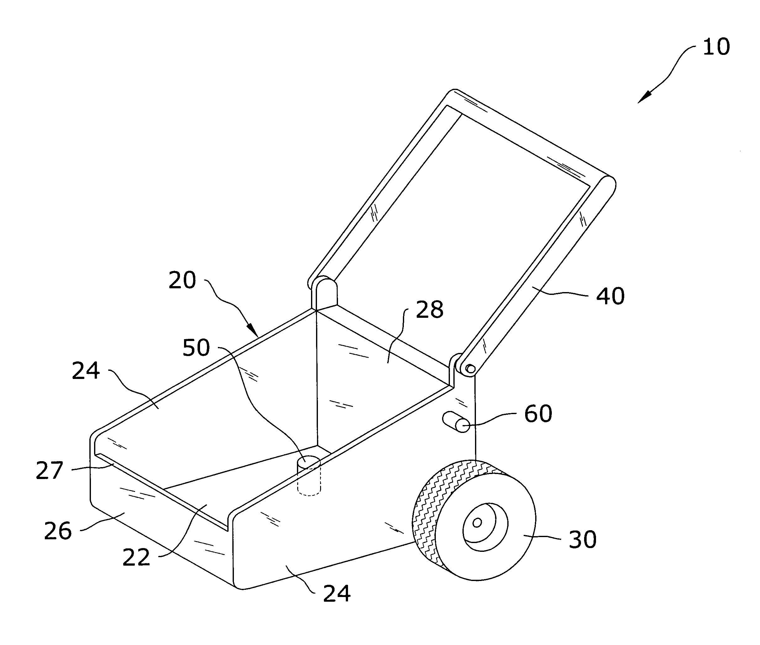
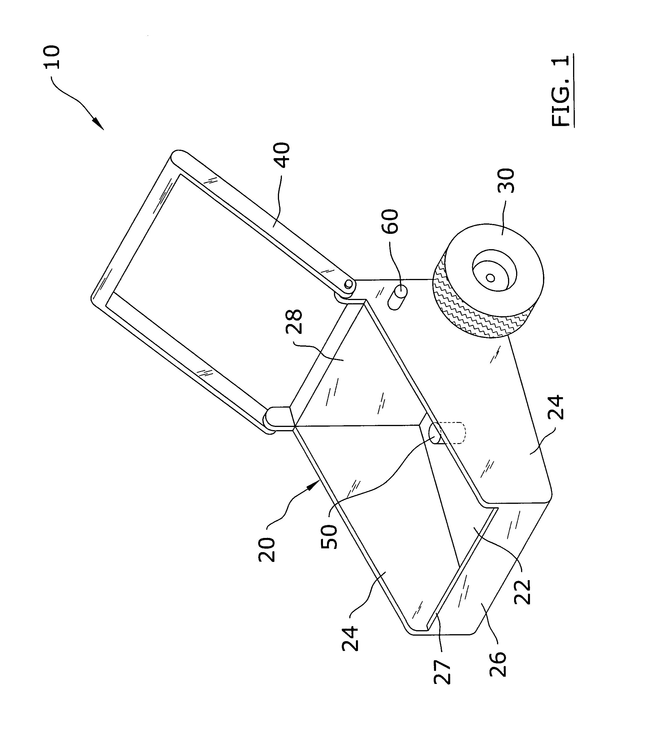
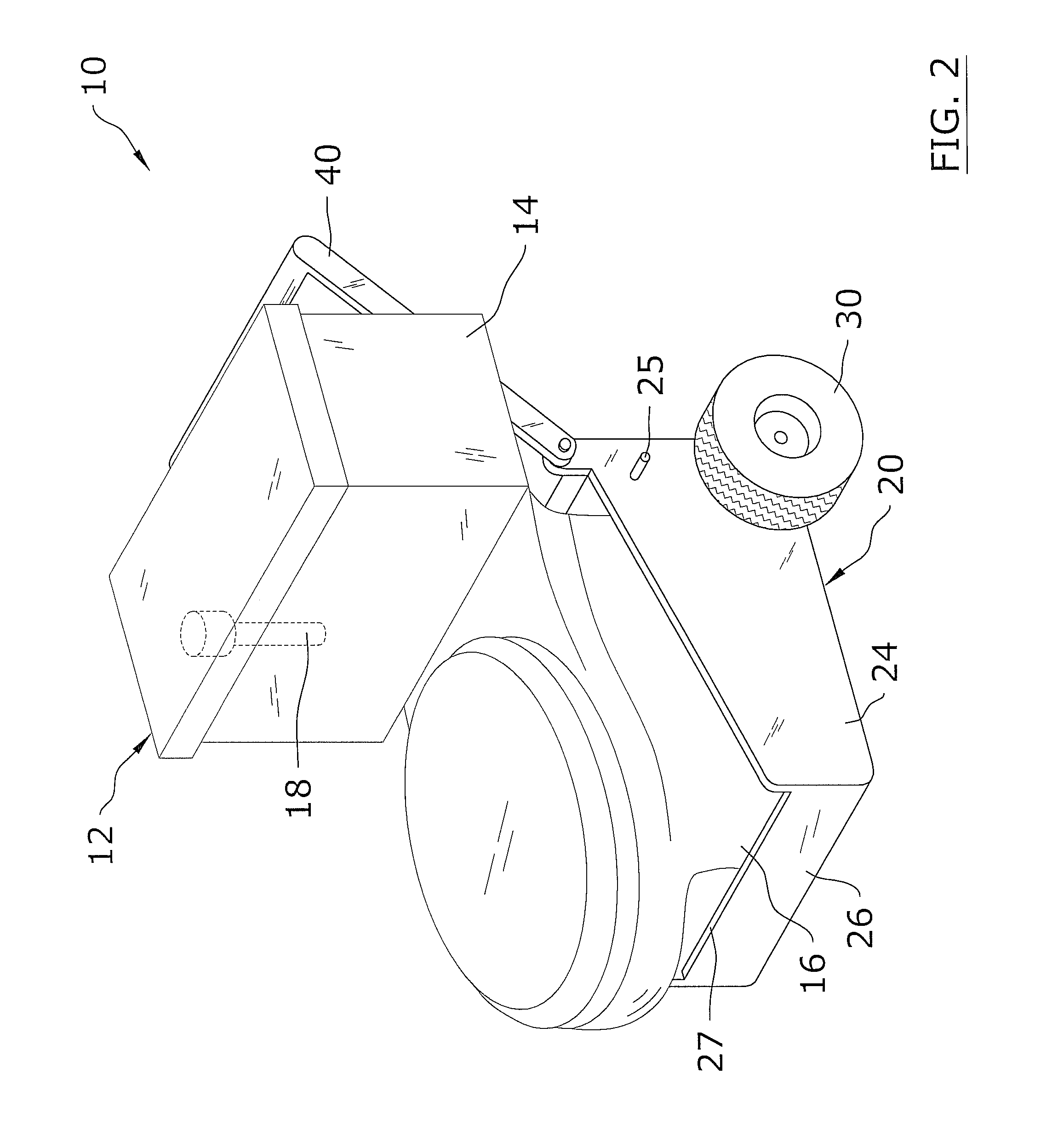
[0033]Turning now descriptively to the drawings, in which similar reference characters denote similar elements throughout the several views, FIGS. 1 through 10 illustrate a toilet moving cart system 10, which comprises a base 20 for receiving a conventional toilet 12, a stub member 50 within the base 20, a plurality of wheels 30 attached to the base 20, and a handle 40 attached to the base 20. The stub member 50 extends upwardly into the lower opening within the toilet 12 when the toilet 12 is positioned upon the base 20. A cap 60 is removably attached to the base 20 for sealing the fill valve 18 within the toilet 12 during transportation to prevent water leakage.

B. Base

[0034]FIGS. 1 through 10 illustrate a preferred embodiment of the base 20 formed for removably receiving and supporting a toilet 12. It can be appreciated that other base 20 structures and combinations of the present structure may be utilized to construct the base 20.

[0035]As best illustrated in FIG. 1 of ...


PUM


Abstract

A toilet moving cart system for efficiently moving a toilet. The toilet moving cart system includes a base for receiving a conventional toilet, a stub member within the base, a plurality of wheels attached to the base, and a handle attached to the base. The stub member extends upwardly into the lower opening within the toilet when the toilet is positioned upon the base. A cap is removably attached to the base for sealing the fill valve within the toilet during transportation to prevent water leakage.

Description

CROSS REFERENCE TO RELATED APPLICATIONS[0001]Not applicable to this application.STATEMENT REGARDING FEDERALLY SPONSORED RESEARCH OR DEVELOPMENT[0002]Not applicable to this application.BACKGROUND OF THE INVENTION[0003]1. Field of the Invention[0004]The present invention relates generally to toilets and more specifically it relates to a toilet moving cart system for efficiently moving a toilet.[0005]2. Description of the Related Art[0006]Any discussion of the prior art throughout the specification should in no way be considered as an admission that such prior art is widely known or forms part of common general knowledge in the field.[0007]Toilets have been in use for years. As shown in FIG. 2 of the drawings, a conventional toilet (12) is typically comprised of a water tank (14), and a bowl (16) having a base and a lower opening fluidly connected to a siphon channel. A fill valve (18) is positioned within water tank to allow the tank to fill to a predetermined height. The lower openin...

Claims


Application Information

Patent Timeline
Patent Type & Authority Patents(United States)
IPC IPC(8): A47K17/00
CPCB62B1/26B62B2202/80
Inventor CERNIK, DAVID A.
Owner CERNIK DAVID A
Why Eureka
Try Eureka