Sealing apparatus with encoder

a technology of sealing apparatus and encoder, which is applied in the direction of mechanical apparatus, instruments, transportation and packaging, etc., can solve the problems of deterioration of detecting accuracy, damage to magnetic encoder or magnetic sensor, and lowering the performance of detecting rotational speed, so as to improve detecting accuracy, improve fitting force, and supply stable magnetic force

Inactive Publication Date: 2007-06-19
NOK CORP
View PDF7 Cites 14 Cited by
  • Summary
  • Abstract
  • Description
  • Claims
  • Application Information

AI Technical Summary

Benefits of technology

[0006]The present invention is made by taking the points mentioned above into consideration, and an object of the present invention is to provide a sealing apparatus integrally formed with a magnetic encoder, which prevents a magnetic force from being lowered or getting out of order caused by an influence of a muddy water, a foreign matter, an external magnetic field or the like making an intrusion into a portion between the magnetic encoder and a magnetic sensor, thereby to make the supply of magnetic force stable. In conjunction therewith, another object of the present invention is to prevent a damage caused by the muddy water or the foreign matter attached to the magnetic encoder or the magnetic sensor so as to prevent a service life of the sealing apparatus from being lowered.
[0015]In the sealing apparatus in accordance with the present invention provided with the structure mentioned above, since the protecting annular member covers the magnetic encoder in the approximately C-shaped manner, the sealing apparatus is not affected by the muddy water, the foreign matter or the like. Further, a relative position in the axial direction can be defined by aligning the respective outer peripheral side end portions of the protecting annular member and the first encoder member with each other, whereby it is possible to assemble without applying any abnormal compression or deformation to the second encoder member. As a result, it is possible to make the supply of magnetic force stable, and it is possible to improve a detecting accuracy for the rotational speed or the like.
[0016]Further, since the first encoder member is fitted to the protecting annular member in one end in the outer peripheral side, the end portion is not exposed to the rolling element side, and only the protecting annular member is fitted to the inner member, it is possible to improve the fitting force between the inner member and the protecting annular member, and it is possible to effectively prevent the grease within the bearing portion from making an intrusion thereinto.
[0017]Further, since the seal lip can be slidable with the first encoder member and the inner peripheral portion of the protecting annular member, and a labyrinth structure can be set between the protecting annular member and the seal member, it is possible to tremendously improve the exclusion of the muddy water, the foreign matter or the like. Further, since the first encoder member is fitted only to the protecting annular member, it is possible to improve the fitting force between both the members, whereby it is also possible to improve a sealing property with respect to the muddy water, the foreign matter or the like. Accordingly, it is possible to prevent the damage caused by the attachment of the muddy water or the foreign matter so as to prevent the service life of the sealing apparatus from being lowered.
[0018]Further, since the second encoder member can be formed to be the largest diameter by setting the labyrinth seal structure between the protecting annular member and the seal member, a detecting range of the magnetic force can be enlarged, whereby it is also possible to improve detecting accuracy.

Problems solved by technology

If the muddy water makes an intrusion thereinto, rust generation is caused, thereby lowering a performance of detecting the rotational speed.
Further, if the foreign matter makes an intrusion thereinto so as to be attached to a portion between the magnetic encoder and the magnetic sensor, there is a risk that the magnetic encoder or the magnetic sensor are damaged due to rotational jamming of the foreign matter in the worst case so as to lead the detected rotational speed into error.
However, in this structure, the muddy water or the foreign matter making an intrusion can not be sufficiently excluded, and there is a problem that the magnetic encoder is exposed to an abnormal compression or deformation at a time when the protection plate integrally formed with the magnetic encoder is assembled, whereby a detecting accuracy is deteriorated.
Further, since the protection plate and the magnetic encoder are fitted and thereafter fitted to the inner member, the fitting force is weakened.
Further, since end portions of the protection plate and the first seal annular member are exposed to the rolling element side, there is a risk that a grease within a bearing portion makes an intrusion from a portion between both the rings.

Method used


Image

  • Sealing apparatus with encoder
  • Sealing apparatus with encoder
  • Sealing apparatus with encoder

Examples


Embodiment Construction

[0022]Next, a description will be given of an embodiment in accordance with the present invention with reference to the accompanying drawings.

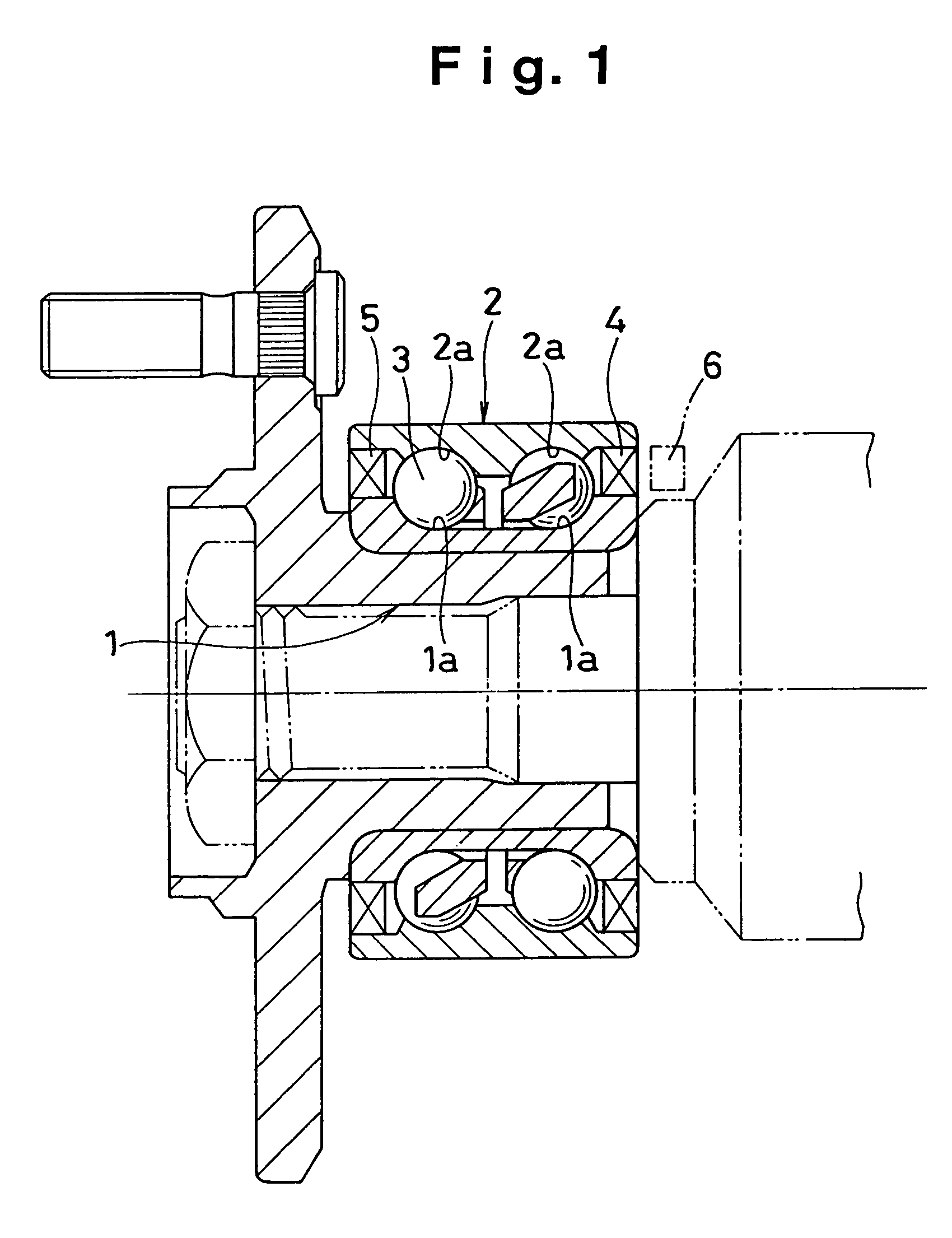
[0023]As shown in FIG. 1, sealing apparatuses 4 and 5 are mounted to both ends so as to closely seal an annular space formed by an inner member 1 and an outer member 2 which are relatively rotated to each other via a rolling element 3. The sealing apparatus 4 in one end is provided with a magnetic encoder for measuring a rotational speed. The inner member 1 and the outer member 2 have raceway surfaces 1a and 2a for the rolling element 3, and each of the raceway surfaces 1a and 2a is formed in a groove shape. The inner member 1 and the outer member 2 may be a bearing inner ring and a bearing outer ring independently, or may be assembled members of the bearing inner ring and the bearing outer ring combined with the other parts respectively. Further, the inner member 1 may be a shaft.

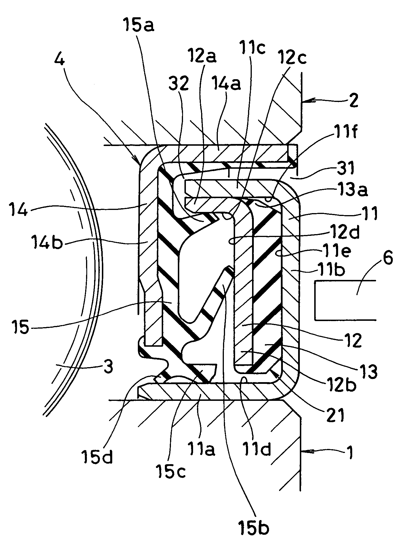
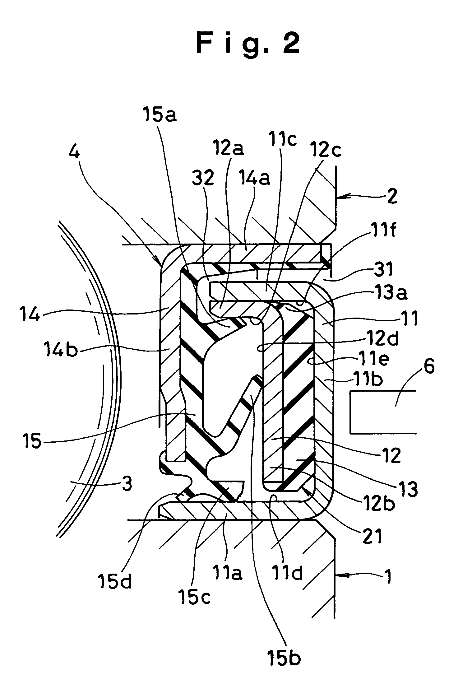
[0024]FIG. 2 shows the sealing apparatus 4 with a magnetic enco...


PUM


Abstract

To prevent lowering and unstableness of magnetic force and trouble caused by influence of muddy water or the like entered between the magnetic encoder (21) and a magnetic sensor (6), a sealing apparatus (4) comprises an approximately C-shaped protecting annular member (11) fitted to one of an inner member (1) and an outer member (2), a first encoder member (12) having a cylinder portion (12a) fitted to the protecting annular member (11), a second encoder member (13) held between the protecting annular member (11) and the first encoder member (12), a seal annular member (14), and a seal member (15) which is vulcanized and bonded to the seal annular member (14) and has seal lips slidably contacting with the protecting annular member (11) and the encoder member (12).

Description

BACKGROUND OF THE INVENTION[0001]1. Field of the Invention[0002]The present invention relates to a structure of a sealing apparatus for closely sealing an annular space formed between an inner member and an outer member which are relatively rotated to each other. More particularly, the present invention relates to a sealing apparatus having a rotation detecting apparatus for detecting a rotational speed of front and rear wheels in an anti lock brake system of a motor vehicle. The sealing apparatus in accordance with the present invention is employed also in a field of an electrical appliance, an industrial machine, a bicycle or the like.[0003]2. Description of Background Art[0004]In conventional, as shown in FIG. 3, there has been developed a sealing apparatus 105 for closely sealing an annular space between an inner member 101 and an outer member 102 which are relatively rotated to each other via a rolling element 103, in which a magnetic encoder 106 is integrally formed with the s...

Claims


Application Information

Patent Timeline
Patent Type & Authority Patents(United States)
IPC IPC(8): F16J15/02
CPCF16C41/007F16J15/326G01P3/443F16C33/7883F16C2326/02F16C19/184
Inventor KOBAYASHI, NAOTO
Owner NOK CORP
Why Eureka
Try Eureka