Adjustable roof jack with flexible boot

Inactive Publication Date: 2007-06-19
HERCULES INE
View PDF3 Cites 16 Cited by
  • Summary
  • Abstract
  • Description
  • Claims
  • Application Information

AI Technical Summary

Benefits of technology

[0010]In view of the foregoing, it is a primary objective of the subject invention to provide an adj

Problems solved by technology

None of the above prior art patents disclose the unique features, functions and adv

Method used


Image

  • Adjustable roof jack with flexible boot
  • Adjustable roof jack with flexible boot
  • Adjustable roof jack with flexible boot

Examples


Embodiment Construction

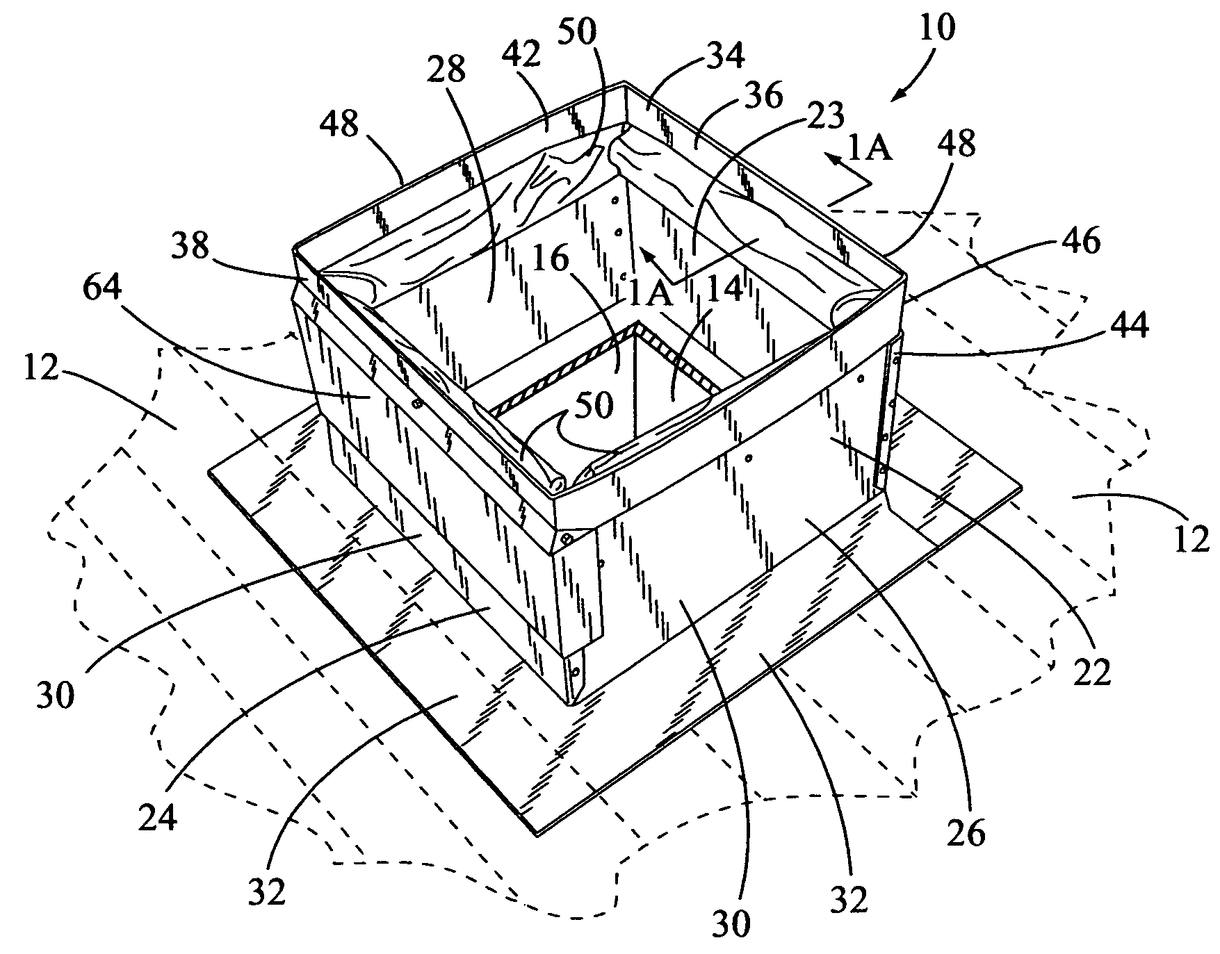
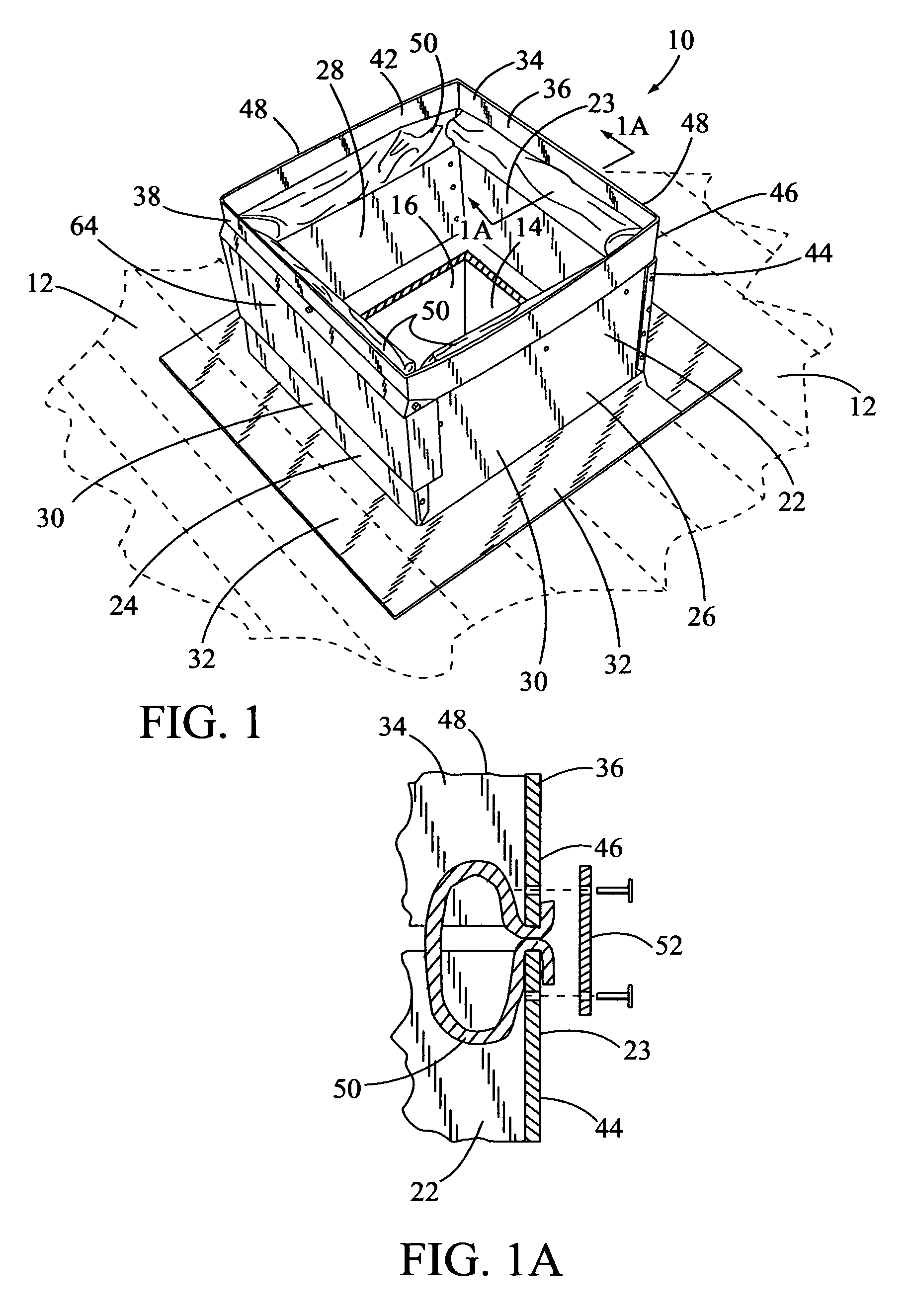
[0022]In FIG. 1, a perspective view of the subject adjustable roof jack is shown having a general reference numeral 10. In this view, the roof jack 10 is mounted on a flat roof 12 and received around a top 14 of an air supply duct 16 in the roof 12. The adjustable roof jack 10 is adapted for receiving a lower end 18 of an air discharge duct 20 from an air conditioning or heating unit. The air conditioning or heating unit is not shown in the drawings. A portion of the air discharge duct 20 is shown in FIGS. 2 and 4.

[0023]The roof jack 10 includes an angular-shaped sheet metal lower frame member 22 having a front side 23, a back side 24, a first side 26 and a second side 28. The front side 23 is typically facing the top of the roof. A lower portion 30 of the sides of the lower frame member 22 is received around the top 14 of the air supply duct 16 in the roof 12. Also, the lower portion 30 of the sides of the lower frame member 22 is integrally formed into an outwardly extending roof ...


PUM


Abstract

An adjustable roof jack adapted for mounting on a flat or pitched roof. The roof jack is connected to a lower end of an air discharge duct from an air conditioning unit and to the top of an air supply duct in the roof. The roof jack includes an angular-shaped sheet metal lower frame member having a front side, back side, a first side and second side. A lower portion of the sides of the lower frame member is received around the top of the air supply duct. Also, the lower portion of the sides of the lower frame member is integrally formed into to an outwardly extending roof flange. The roof jack also includes an angular-shaped sheet metal upper frame member having a front side, a back side, a first side and second side. A top portion of the front side of the upper frame member is hinged to a bottom portion of the front side of the upper frame member. A flexible boot is attached to an inside of the top portion of the sides of the lower frame member and to an inside of a lower portion of the sides of the upper frame member. The flexible boot is adapted for receipt around a portion of the air discharge duct.

Description

BACKGROUND OF THE INVENTION[0001](a) Field of the Invention[0002]This invention relates to a roof jack for connecting an air discharge duct from a roof mounted air conditioning unit to an air supply duct in a roof of a building and more particularly, but not by way of limitation, to an adjustable roof jack with a flexible boot for receiving a portion of the air discharge duct therein. The roof jack is adaptable for both flat and different pitch roofs.[0003](b) Discussion of Prior Art[0004]Heretofore, there have been various designs and shapes of roof jacks used with roof mounted evaporative coolers, air conditioning units, heat pumps and the like mounted on flat and pitched building roofs.[0005]In U.S. Pat. No. 5,409,266 to Baker, an adjustable roof jack is disclosed. The roof jack includes an upper rectangular box-like member pivotally attached to a lower rectangular box-like member. The pivot points are located intermediate the front and back of the two members.[0006]In U.S. Pat. ...

Claims


Application Information

Patent Timeline
IPC IPC(8): F24F7/00
CPCE04D13/1471E04D13/1475F24F7/02
Inventor NEWELL, KENT
Owner HERCULES INE
Why Eureka
Try Eureka