
Oven liner

a liner and oven technology, applied in the field of oven liner, can solve the problems of arcing and/or other damage, low practical use of liner in a heavily used commercial oven, and high cost of subsequent repairs, and achieve the effect of facilitating ridging

Inactive Publication Date: 2007-06-19
REGALE MICROWAVE OVENS
View PDF8 Cites 4 Cited by
  • Summary
  • Abstract
  • Description
  • Claims
  • Application Information

AI Technical Summary

Benefits of technology

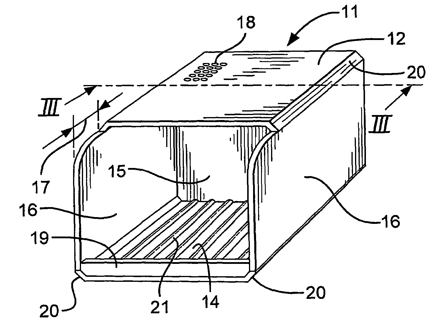
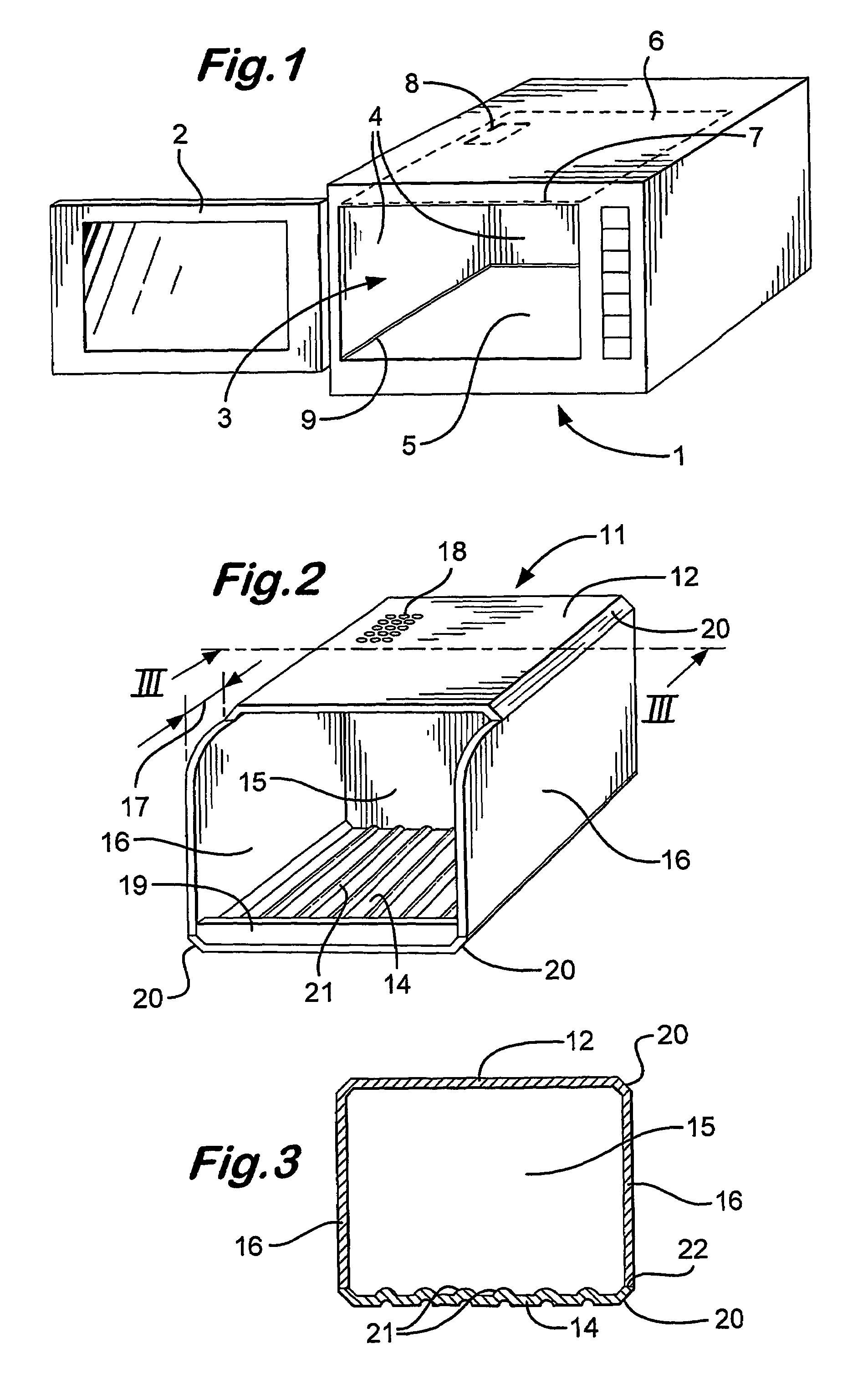
[0013]A second preferred feature of the preferred embodiment is a series of ridges on the floor of the liner. Conveniently, the ridges extend from front to back. Preferably they are rounded, typically standing up to 5 mm high and usually being 2 mm high and being spaced between 5 mm and 20 mm apart and usually being 10 mm apart. The effect of these ridges is to raise a vessel containing food to be heated off the floor. Thus air is allowed to flow beneath the vessel. This helps to eliminate “hot spots”.
[0014]It is also preferred that the floor of the liner should be slightly thicker than the sides, back and roof, which facilitates the ridging.

Problems solved by technology

Unless these deposits are scrupulously cleaned off at the end of the day, they can build up to the extent that they desiccate and cause arcing and / or other damage.
Subsequent repairs can be expensive.
However, such a liner is of little practical use in a heavily used commercial oven.

Method used


Image

  • Oven liner
  • Oven liner
  • Oven liner

Examples


Embodiment Construction

[0026]Referring to FIGS. 1 to 3 of the drawings, a conventional microwave oven 1 has a glass panelled door 2 (shown open) with a cavity 3 lined with steel side and back walls 4, a ceramic floor 5 and a thin plastics moulding roof 6. A gap 7 is provided at the front between the door and the roof, whilst a further aperture 8 is provided in the roof. These are for air circulation by a non-shown fan. A silicon seal 9 seals the floor to the side walls. Non-shown microwave emitters and stirrers are provided above the roof and below the floor.

[0027]A liner 11 of the invention is an injection moulding of approximately 5 mm thick elements, namely:[0028]a roof 12,[0029]a floor 14,[0030]a back 15 and[0031]two sides 16.

The moulding is of food grade polypropylene, such that the liner can be washed in a commercial dishwasher.

[0032]The liner is sized to be a sliding fit in the oven. Due to its modest wall thickness, it reduces the capacity of the oven by a small amount only, yet is sufficiently ri...


PUM


Abstract

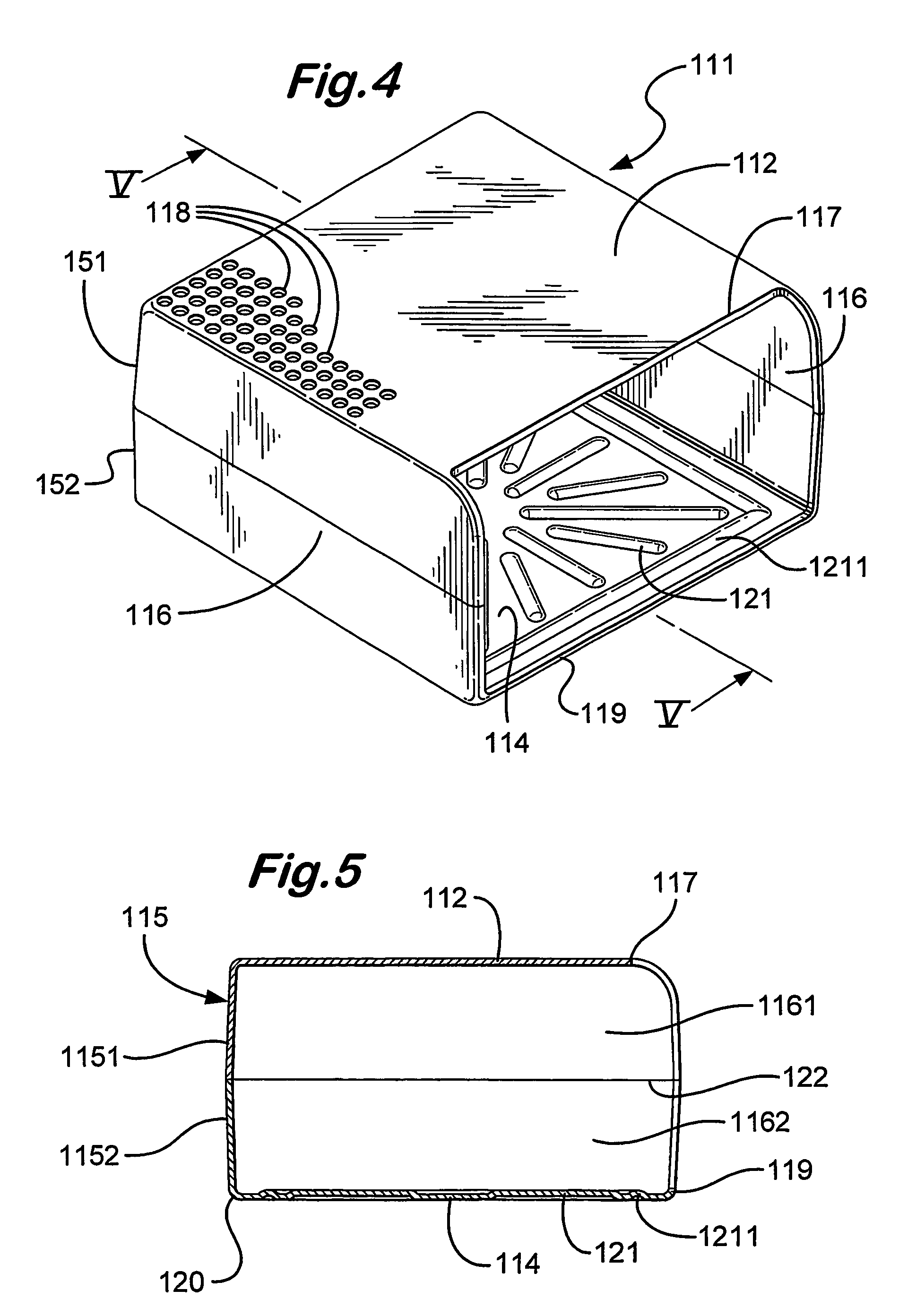
A microwave oven liner 11 is an injection moulding having a roof 12, a floor 14, a back 15 and two sides 16. The moulding is of food grade polypropylene, such that the liner can be washed in a commercial dishwasher. The liner is sized to be a sliding fit in a microwave oven. The roof is shorter 17 at the front than the floor to allow air circulation. Further, the roof is apertured, also for air circulation, with a series of small c. 4 mm bores 18 registering with the roof aperture 8. A lip 19 is provided across the front of the floor to retain split liquid. The external corners 20 are chamfered to clear the silicone seal 9 for instance. The floor has regularly pitched, 2 mm high ridges 21 running front to back. The ridges allow circulation of air beneath a container of food being heated in the oven having the liner.

Description

CROSS REFERENCE TO RELATED APPLICATIONS[0001]This application is for entry into the U.S. national phase under §371 for International Application No. PCT / GB03 / 003411 having an international filing date of Aug. 4, 2003, and from which priority is claimed under all applicable sections of Title 35 of the United States Code including, but not limited to, Sections 120, 363 and 365(c), and which in turn claims priority under 35 USC §119 to British Patent Application No. GB0306010.0 filed on Mar. 17, 2003, which in turn claims the priority of British Patent Application No. GB0218160.0 filed on Aug. 6, 2002.TECHNICAL FIELD[0002]The present invention relates to an oven liner, in particular a liner for a microwave oven.BACKGROUND OF THE INVENTION[0003]In commercial microwave ovens, which are most heavily used than domestic microwaves ovens, spits of food can become deposited around the oven, particularly on the inside walls of the oven. Unless these deposits are scrupulously cleaned off at the...

Claims


Application Information

Patent Timeline
Patent Type & Authority Patents(United States)
IPC IPC(8): H05B6/80F24C15/00A47J36/02F24C7/02
CPCA47J36/027F24C15/007H05B6/6426Y10S99/14
Inventor BRAY, PATRICK LEON
Owner REGALE MICROWAVE OVENS
Learn More