Method and apparatus for providing a temporary utility zone in a disk drive

a technology for disk drives and utility zones, applied in the field of data storage devices, can solve the problems of increasing the demands on stw, and reducing the use value of stw

Inactive Publication Date: 2007-06-19
MAXTOR
View PDF3 Cites 10 Cited by
  • Summary
  • Abstract
  • Description
  • Claims
  • Application Information

AI Technical Summary

Problems solved by technology

The STW is an expensive piece of capital equipment, and even a small reduction in the servo information needed to be written by the STW can result in significant time and cost savings.
Furthermore, as the tracks per inch (TPI) increases, the servo write time increases since the STW makes more circumferential passes over the disk, thereby increasing the demands on the STW.
Unfortunately, a discontinuity may occur in the certified region between the final servo information and the utility zone.
In addition, handling the disk drive (such as moving it from station-to-station) may cause alignment changes (such as spindle tilt).
Furthermore, accessing the special drive code may delay the seek operations, thereby degrading the performance of the disk drive.

Method used


Image

  • Method and apparatus for providing a temporary utility zone in a disk drive
  • Method and apparatus for providing a temporary utility zone in a disk drive
  • Method and apparatus for providing a temporary utility zone in a disk drive

Examples


Embodiment Construction

[0038]While embodiments of the present invention are susceptible of many different forms, there are shown in the drawings and will herein be described in detail, preferred embodiments of the invention with the understanding that the present disclosure is to be considered as an exemplification of the principles of the embodiments and is not intended to limit the broad aspects of the embodiments to those illustrated.

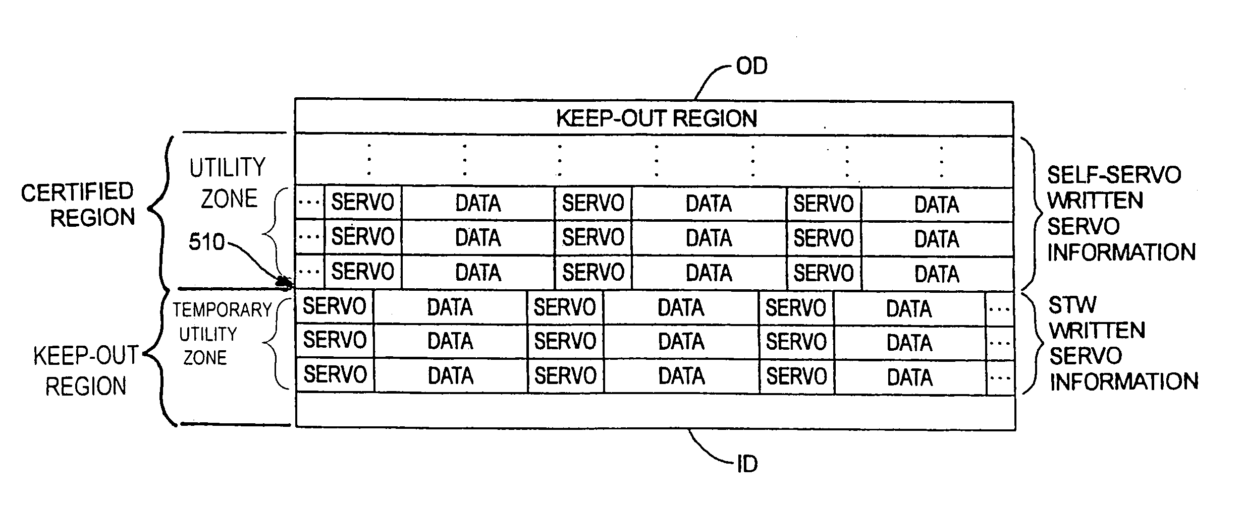
[0039]FIG. 5A diagrammatically depicts, and FIG. 6 is a flowchart 600 illustrating, self-servo writing that avoids a discontinuity between the final servo information and the utility zone.

[0040]The disk drive is placed in a first station that includes a STW (step 610). The STW is used to write a small band of final embedded servo information in a circumferential fashion in the keep-out region of the disk. The STW is also used to write temporary spiral servo information, adjacent to the small band of embedded servo information, across the certified region. Thus, instead of ...


PUM

PropertyMeasurementUnit
radiusaaaaaaaaaa
inner diameteraaaaaaaaaa
outer diameteraaaaaaaaaa

Abstract

A disk surface has a keep-out region and a certified region. A transducer associated with the disk surface writes servo information in the keep-out region under control of a servo track writer. The transducer then writes data in a temporary utility zone in the keep-out region. Next, a self-servo write operation uses data in the temporary utility zone to write servo information in the certified region. Thereafter, data is transferred from the temporary utility zone to a final utility zone in the certified region.

Description

CROSS-REFERENCE TO RELATED APPLICATIONS[0001]This application claims priority from U.S. Provisional Application Ser. No. 60 / 475,097 filed Jun. 2, 2003, which is incorporated herein by reference in its entirety.FIELD OF THE INVENTION[0002]The embodiments of the present invention relate generally to data storage devices, and more particularly to providing a temporary utility zone in a disk drive.BACKGROUND OF THE INVENTION[0003]Disk drives store information on magnetic disks. Typically, the information is stored in concentric tracks on the disk and the tracks are divided into servo sectors that store servo information and data sectors that store customer data. A transducer (head) reads from and writes to the disk. The transducer is mounted on an actuator arm that moves the transducer radially over the disk. Accordingly, the actuator arm allows the transducer to access different tracks on the disk. The disk is rotated by a spindle motor at high speed which allows the transducer to acce...

Claims


Application Information

Patent Timeline
Patent Type & Authority Patents(United States)
IPC IPC(8): G11B21/02G11B5/09
CPCG11B5/59661G11B5/59666G11B5/59688
Inventor REWERTS, DAVIDLIIKANEN, BRUCEVANLAANEN, JOHN
Owner MAXTOR
Why Eureka
Try Eureka