Tunnel reroute

a tunnel and tunnel technology, applied in the field of realtime data transfer, can solve the problems of loss of one or more frames of video, tcp data packets sent on different paths may not arrive in order, and the internet is not designed for realtime data transfer, so as to achieve efficient switching data transfer

Inactive Publication Date: 2007-06-19
CISCO TECH INC
View PDF13 Cites 64 Cited by
  • Summary
  • Abstract
  • Description
  • Claims
  • Application Information

AI Technical Summary

Benefits of technology

[0011]The present invention relates to efficiently switching data transfer from a first reserved communications path to a second reserved communications path. The second communications path is enabled before the first communications path is disabled.

Problems solved by technology

However, the Internet is not designed for realtime data transfer.
Due to congestion in nodes along paths from the source node to the destination node, TCP data packets sent on different paths may not arrive in order.
If a data packet does not arrive at the destination node in time this delayed packet may be noticeable, for example, a delay in a data packet for live video may result in a loss of one or more frames of the video.
A disruption in service may occur in the tunnel, for example, due to a hardware failure in one or more nodes, or a connection between nodes, requiring the tunnel to switch data transfer to a new path between the source node and the destination node.
If the new path requests a resource reservation in a shared intermediate node before the old path has released the resource in the shared node, the resource is not available for the new path.

Method used


Image

  • Tunnel reroute
  • Tunnel reroute
  • Tunnel reroute

Examples


Embodiment Construction

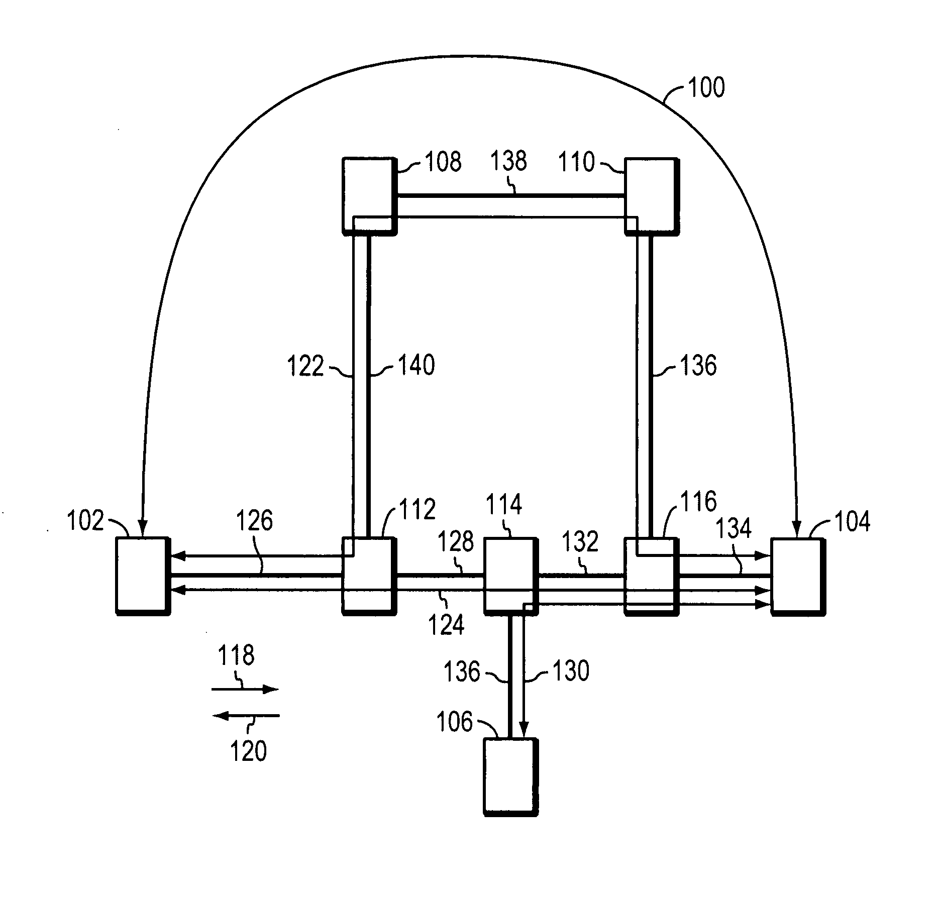
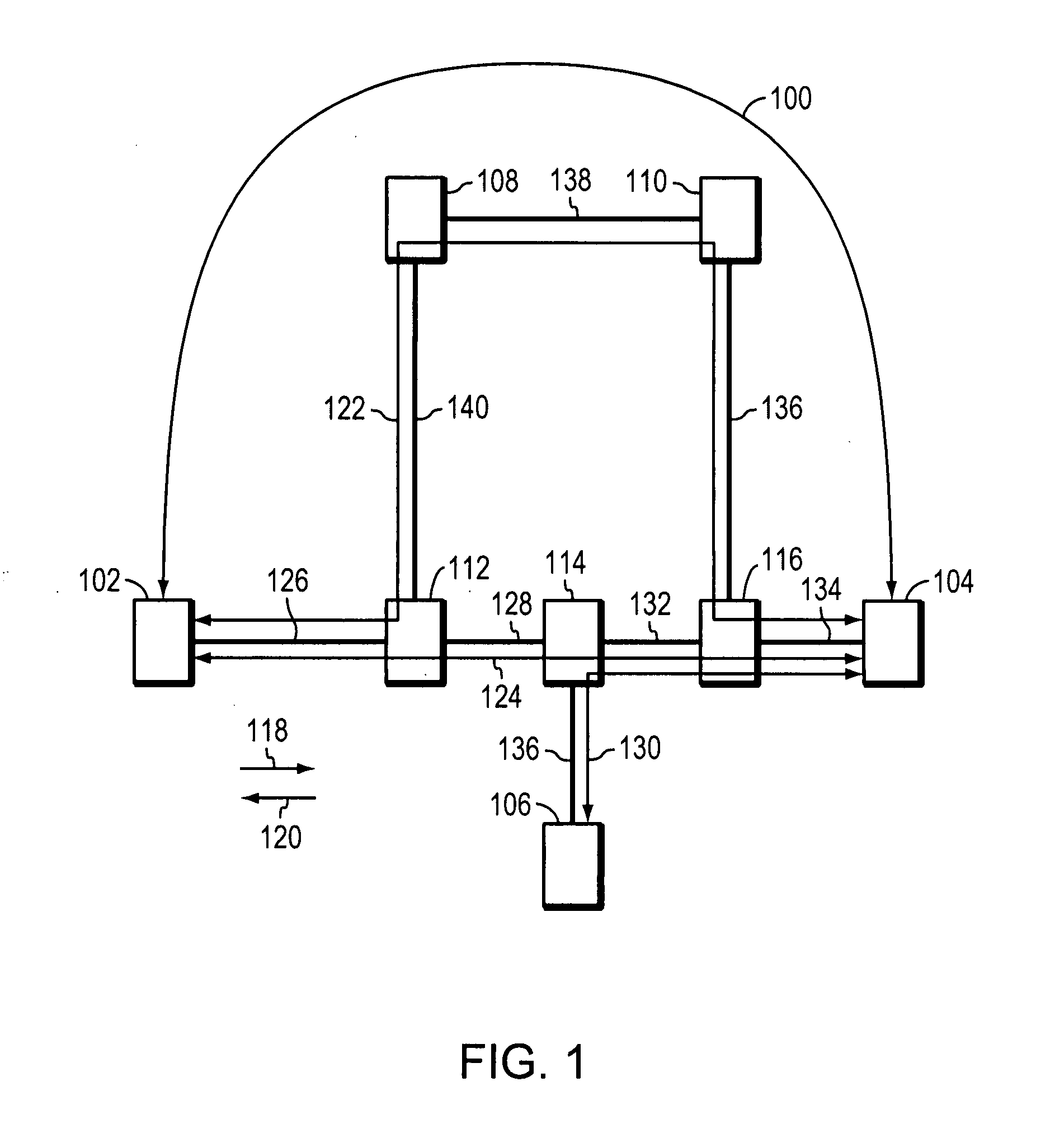
[0024]FIG. 1 shows a tunnel 100 connecting a first source node 102 and a destination node 104. Tunnel 100 includes a first path 124 and a second path 122. Data transfer for tunnel 100 may be enabled through the first path 124 or the second path 122. Tunnel 100 includes nodes 102, 104, 112, 114, 116, 108 and 110 connected by bi-directional communications links 126, 128, 132, 134, 140, 138 and 136. The nodes 102, 104, 112, 114, 116, 108 and 110 may be host computers or routers. Data packets are transferred between nodes 102, 104, 112, 114, 116, 118 and 110 on communication links 126, 128, 132, 134, 140, 138 and 136 using a network protocol such as, TCP / IP.

[0025]For example, if data transfer for tunnel 100 is enabled through the first path 124, data packets from the first source node 102 are transmitted on communications link 126 to intermediate node 112, from intermediate node 112 on communications link 128 to intermediate node 114, from intermediate node 114 on communications link 13...


PUM


Abstract

In a tunnel connecting a source node to a destination node, data transfer for the tunnel is enabled through a first path. The data transfer is enabled by reserving resources in intermediate nodes in the first path between the source node and the destination node. Data transfer for the tunnel may be switched from the first path to a second path by reserving resources in intermediate nodes in the second path. If an intermediate node in the second path is shared by the second path and the first path, the resources reserved by the first path are shared by the second path. If an intermediate node in the second path is not shared by the first path, resources are reserved by the second path. After resources are reserved in the second path and data transfer is enabled in the second path, data transfer for the tunnel is switched to the second path.

Description

BACKGROUND OF THE INVENTION[0001]There is a growing need for realtime data transfer on the Internet to support realtime applications such as, teleconferencing and live video. However, the Internet is not designed for realtime data transfer. Data is transferred on the Internet using Transmission Control Protocol (“TCP”) / Internet Protocol (“IP”). TCP / IP includes four layers, the application layer, the transport layer, the network layer and the link layer.[0002]Data originates in the application layer, for example, the application data may be frames of a live video to be transmitted from a source node to a destination node. The transport layer includes the TCP protocol. The TCP protocol in the source node processes the frames of the live video into TCP data packets and assigns a sequence number to each packet of data. The TCP protocol in the destination node reassembles the TCP data packets transmitted by the source node using the data packet's sequence numbers.[0003]The network layer ...

Claims


Application Information

Patent Timeline
Patent Type & Authority Patents(United States)
IPC IPC(8): H04L1/00H04L12/26
CPCH04L12/4633H04L12/5695H04L45/128H04L45/22H04L45/30H04L47/724H04L47/825H04L47/70
Inventor SWALLOW, GEORGE
Owner CISCO TECH INC
Why Eureka
Try Eureka