
Telecommunications connection cabinet

a technology for connecting cabinets and telecommunications, which is applied in the field of cabinets, can solve the problems of affecting the transmission of light to and from optical fibers, connectors that are not capable of being received in known optical fiber adapters, and adapters that are not as effective in protecting the polished end faces as dust caps

Inactive Publication Date: 2007-06-19
COMMSCOPE TECH LLC
View PDF76 Cites 299 Cited by
  • Summary
  • Abstract
  • Description
  • Claims
  • Application Information

AI Technical Summary

Benefits of technology

The patent text describes a telecommunications cabinet and a connection rack that allow for the optical connection of fiber optic cables. The cabinet includes a cable management structure and an adapter panel with a fiber optic connector holder for inserting fiber optic connectors. The connection rack includes a fanout module, an adapter module, a connector holder module, and a cable management structure. The method involves directing a multi-strand optical fiber service cable to the fanout module, separating the fibers into individual patch cords, and connecting them to the cable management structure. The technical effects of this patent include improved management of fiber optic cables and connectors, simplified installation, and improved optical connection efficiency.

Problems solved by technology

Such contaminants which might adversely impact the transmission of light to and from the optical fiber include but are not limited to dust and finger prints.
However, when such dust caps are in place, the connector is not capable of being received in known optical fiber adapters, such as those described in U.S. Pat. Nos. 5,317,663, and 6,347,888.
While the adapters might provide some protection from contaminants to a single connector inserted into an adapter, these adapters are not as effective as a dust cap in protecting the polished end face.

Method used


Image

  • Telecommunications connection cabinet
  • Telecommunications connection cabinet
  • Telecommunications connection cabinet

Examples


Embodiment Construction

[0063]Reference will now be made in detail to exemplary aspects of the present invention which are illustrated in the accompanying drawings. Wherever possible, the same reference numbers will be used throughout the drawings to refer to the same or similar parts.

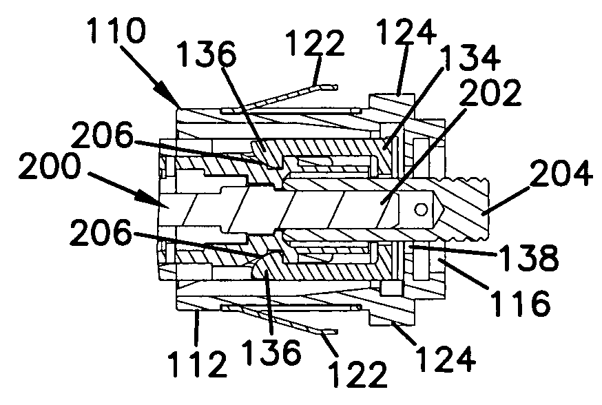
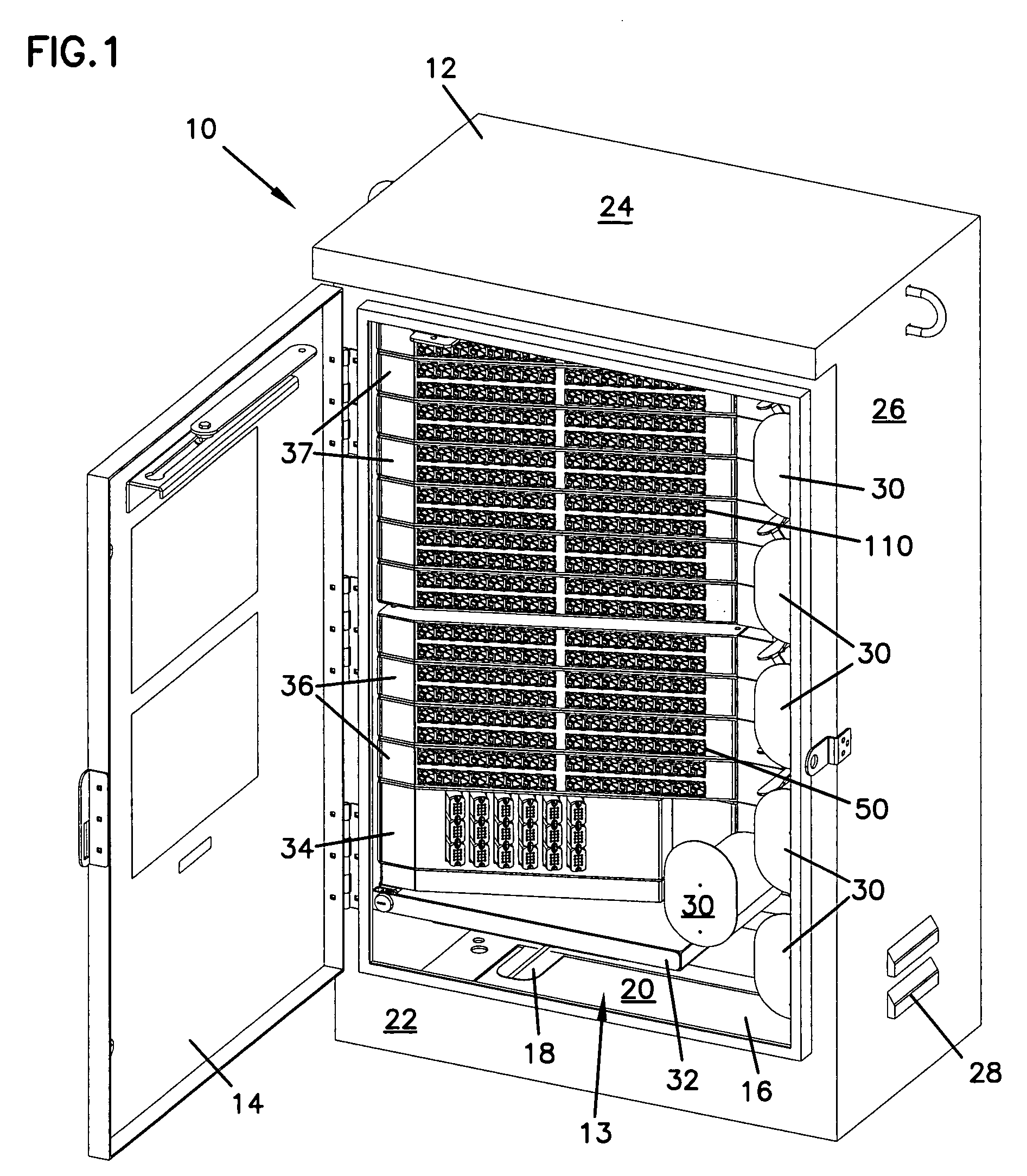
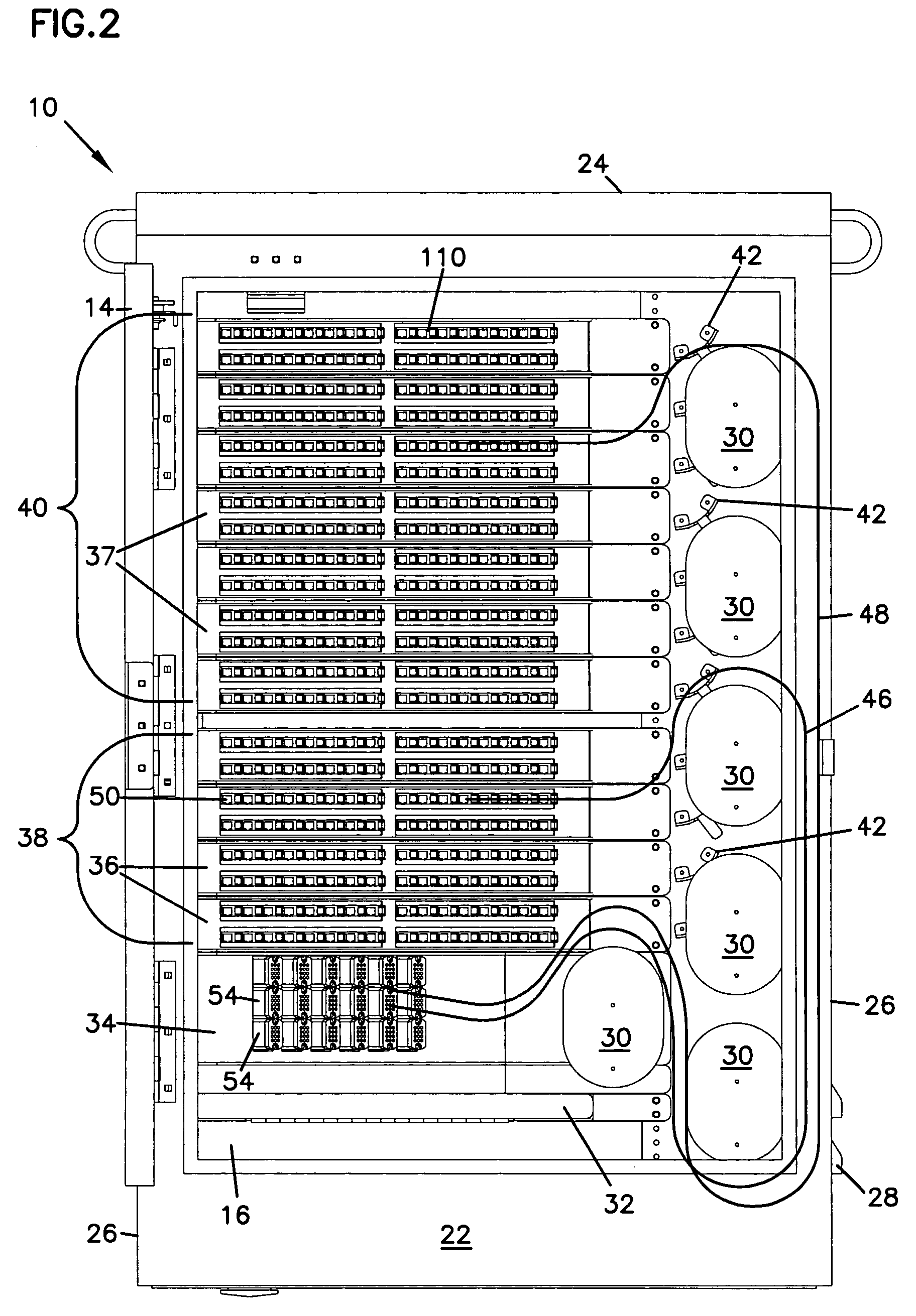
[0064]Telecommunications connection cabinets, such as cabinet 10 shown in FIG. 1, are used to permit organization and interconnection of different telecommunications infrastructure cables. A multi-strand telecommunications service cable such as an IFC or ribbon cable with multiple optical fibers, may be used to electronically or optically link widely spaced facilities. The service cable may be directed into cabinet 10 where it may be connected to a fanout module 34 and separated into individual fibers. Each of these strands may be connected to a patch cord 46 which may be terminated with a fiber optic connector. The fiber optic connector of patch cord 46 (such as connector 200 described below) may then be inserted into the fr...


PUM

PropertyMeasurementUnit
sizeaaaaaaaaaa
sizeaaaaaaaaaa
storage areaaaaaaaaaaa

Abstract

A telecommunications cabinet comprising a top, a floor, a pair of opposing sides, a front wall and a rear wall defining an interior, the front including an access door for accessing the interior. Within the interior are mounted a cable management structure, an adapter panel with an adapter configured to optical connector two optical fiber cables terminated with fiber optic connectors, and a fiber optic connector holder mounted in openings of the adapter panel. The connector holder has an opening configured to receive a fiber optic connector with a dust cap, the opening accessible from a front side of the adapter panel. A fiber optic connector including a ferrule with a polished end face holding an end of an optical fiber with a dust cap placed about the ferrule and polished end face is inserted within the opening of a fiber optic connector holder. And a fiber optic connector is inserted within the rear side of one of the adapters.

Description

FIELD OF THE INVENTION[0001]The present invention generally relates to cabinets for connecting telecommunications cables.BACKGROUND OF THE INVENTION[0002]Installation of telecommunications equipment to support the current and potential future needs of a particular group of customers may make it desirable to install more capacity than the current customer base alone may dictate. Excess capacity may be installed to permit the easy addition of new circuits for new or existing customers. A telecommunications connection cabinet with such excess capacity may be pre-configured at a fabrication facility and installed in the field to include more circuits than are necessary to provide service to the existing customers. Prior to the linkage of these surplus or future expansion circuits to customers, it is desirable to provide for storage, organization and protection of the patch cords or other connection cables within the cabinet.[0003]Such connection cables might include fiber optic patch co...

Claims


Application Information

Patent Timeline
Patent Type & Authority Patents(United States)
IPC IPC(8): G02B6/00G02B6/38G02B6/44H04Q1/14
CPCG02B6/3849G02B6/4452G02B6/4446G02B6/46G02B6/4471G02B6/4478G02B6/4442G02B6/3893G02B6/3897H04Q2201/804Y10T29/49826G02B6/44528G02B6/44526H05K7/02G02B6/445G02B6/3879G02B6/4457
Inventor SOLHEID, JAMES J.MERTESDORF, DANIEL RAYHOLMBERG, MATTHEW J.SMITH, TREVOR D.DOUGLAS, JOEL B.BARNES, KATHLEEN M.HOLMQUIST, MARLON E.
Owner COMMSCOPE TECH LLC
Learn More