Brewer system with brew status indicator and method
Inactive Publication Date: 2007-06-26
FOOD EQUIP TECH
View PDF5 Cites 41 Cited by
Summary
Abstract
Description
Claims
Application Information
AI Technical Summary
This helps you quickly interpret patents by identifying the three key elements:
Problems solved by technology
Method used
Benefits of technology
[0012]Obtainment of the object is achieved by providing in a brewing system having a brew cycle start switch to start a brew cycle and a brew cycle status light associated with the start switch, with a brew cycle status light controller having means for causing the light to operate in a first mode of operation if the brew cycle start switch has not been activated to start a brew cycle, m
Problems solved by technology
Because of these electrical power requirements, the brewing rate of known high volume systems is limited by the level of electrical power service available at the brewing site.
Turning to another problem with known twin brewing systems, should the single controller or its single power supply fail, both sides of the twin brewers and thus the entire brewing system becomes complet
Method used
Image
Click on the blue label to locate the original text in one second.
Reading with bidirectional positioning of images and text.
Examples
Embodiment Construction
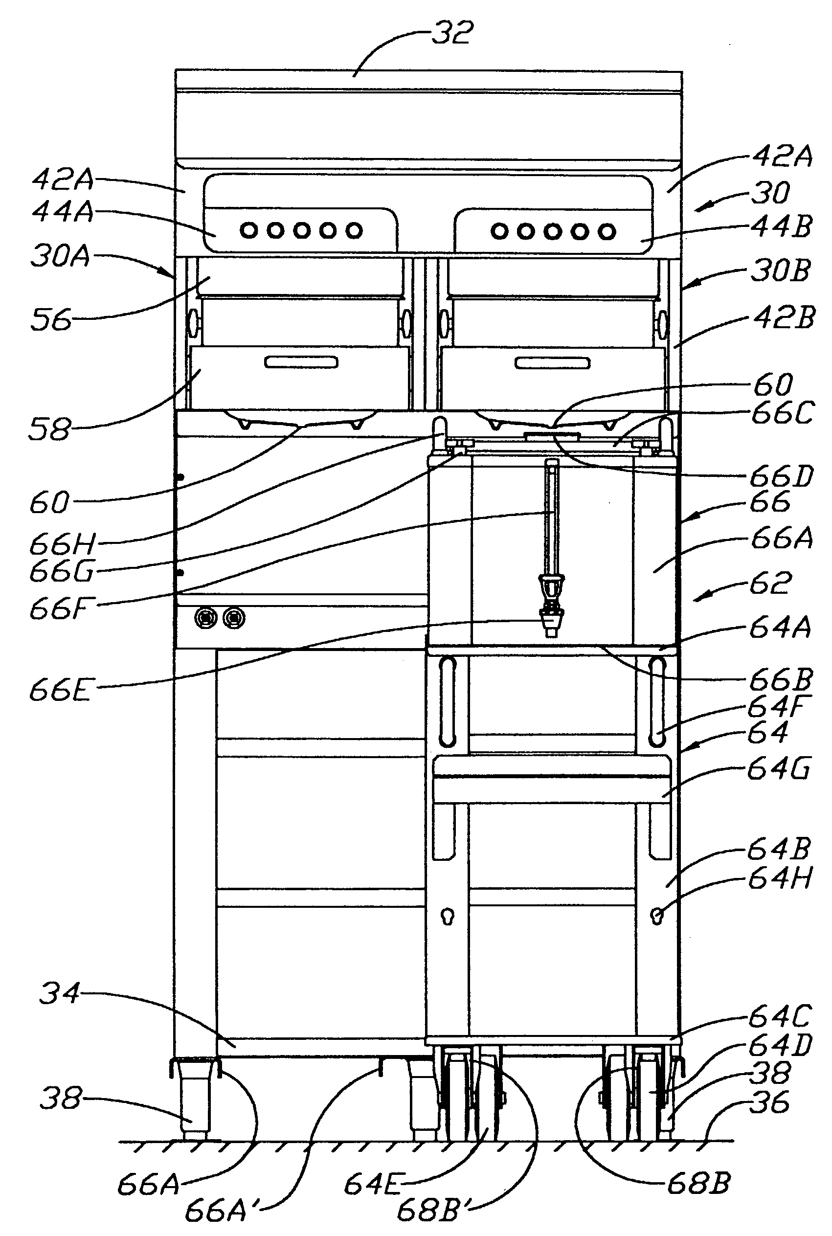
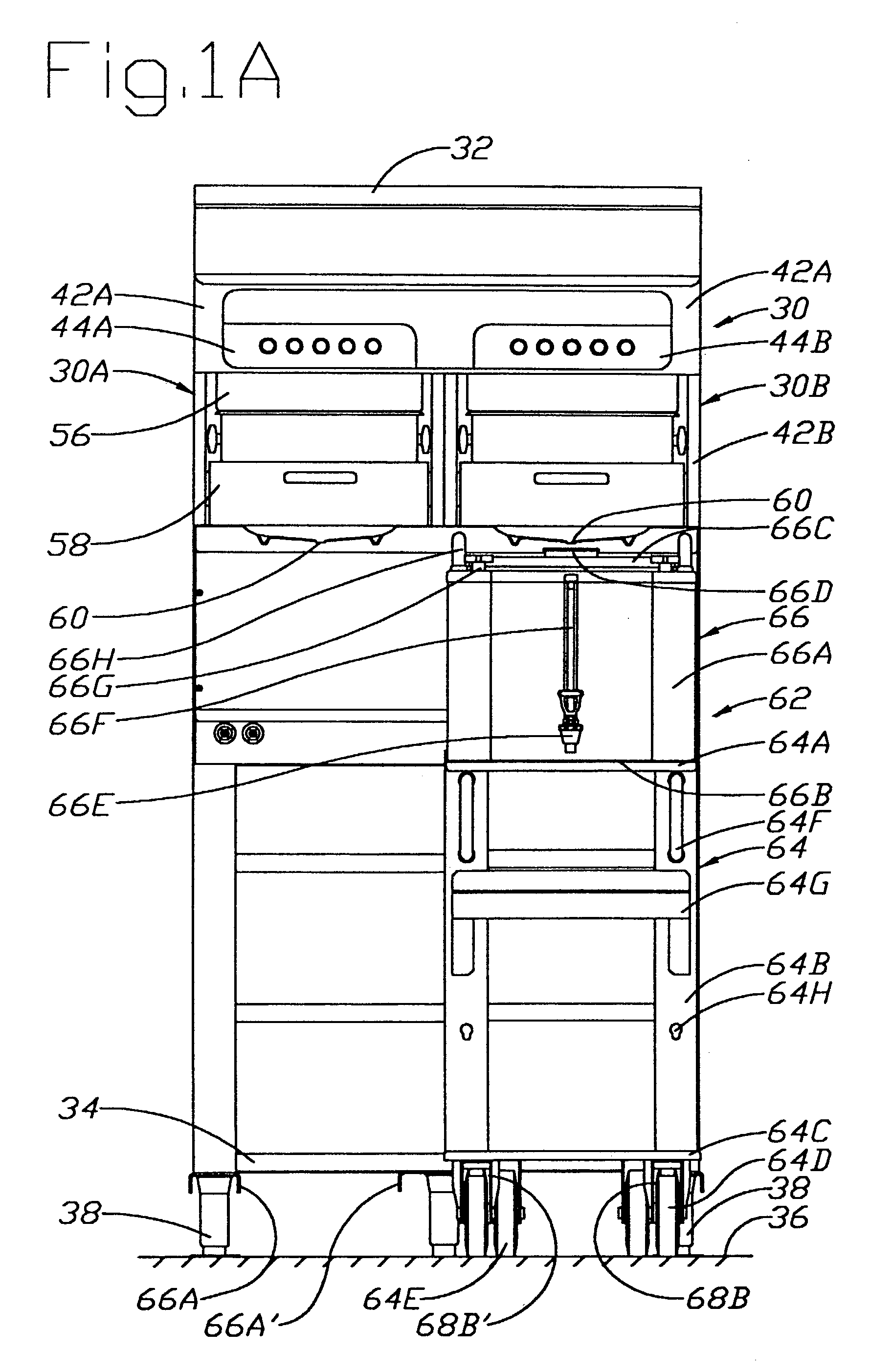
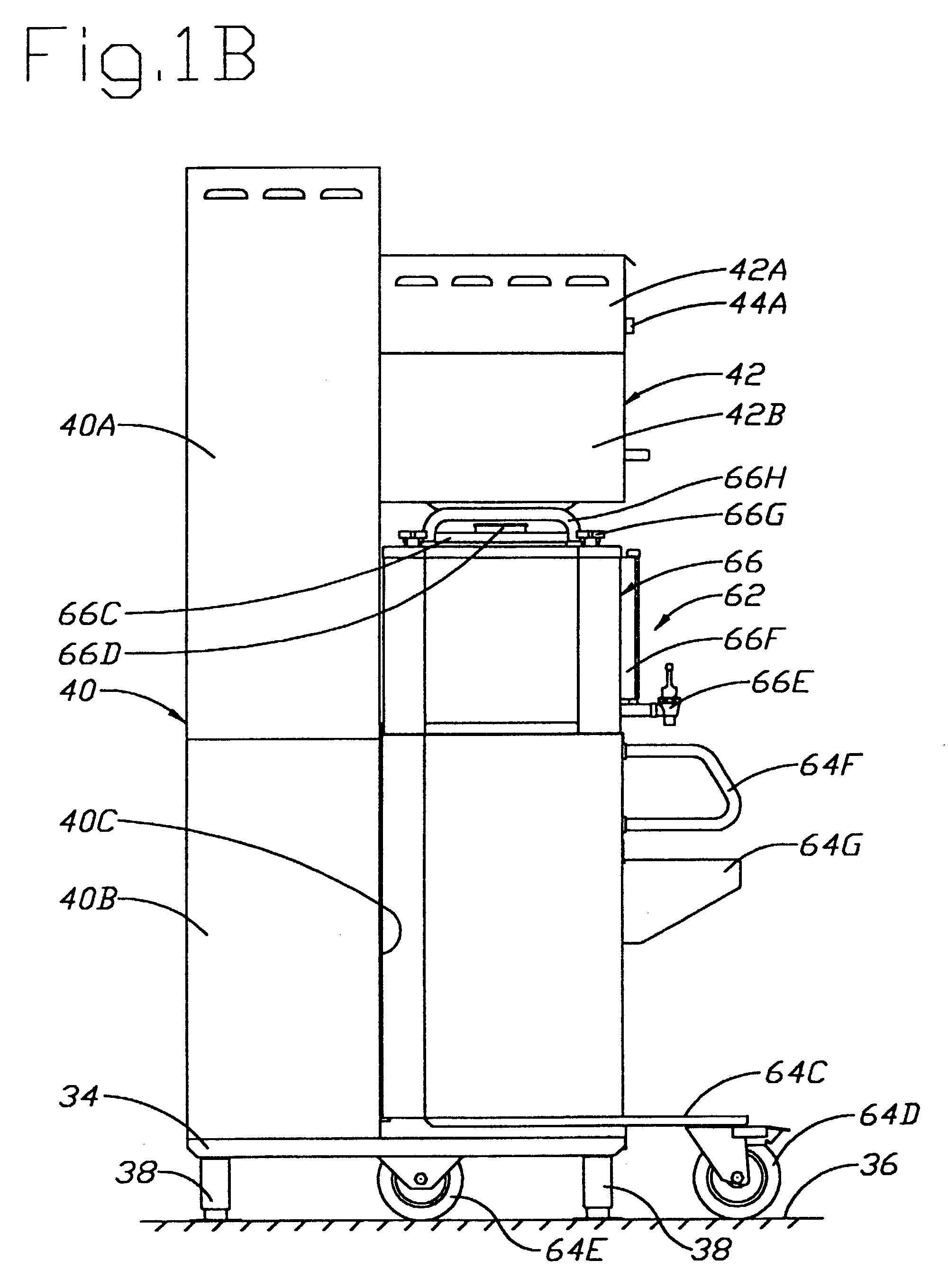
[0047]Referring to FIGS. 1A, B and 1C, a preferred embodiment of a mobile twin brewer system 30 is seen which includes a pair of substantially identical brewers 30A and 30B symmetrically mounted in side-by-side symmetrical relationship within a single rectilinear housing, or frame, 32. The rectilinear housing includes a base 34 supported above a floor 36 by five substantially identical legs 38, and the base 34 supports an elongate, upright aft housing section 40 with an upper aft housing portion 40A and a lower aft housing portion 40B.
[0048]The upper aft housing portion 40A, in turn, supports a forward housing section 42 in cantilever relationship suspended at a preselected relatively elevated position above the floor 36, as best seen in FIG. 1B. The cantilevered forward housing section has an upper cantilevered housing portion 42A and a lower cantilevered housing portion 42B. Mounted to the forward face of the upper cantilevered housing portion are two control panels 44A and 44B of...
PUM
Abstract
A twin brewer system (30) with a pair of brewers (30A, 30B) each with a controller (158) for controlling the application of electrical power to a hot water heater, disables the application of electrical power to the heater (154) of one brewer (30A, 30B) in response to actuation of a start brew switch of the one brewer (30A, 30B) while electrical power is being applied to the heater (154) of the other brewer (30A, 30B). The controllers also respond to a hot water quantity sensor (164, 168) and a responsive delay circuit for disabling dispensing of hot water in response to actuation of the brew start switch (50) until a sufficient quantity of hot water is in a hot water dispenser tank (152) needed for the brew cycle. Indication lamps indicate when the brew cycle is being delayed and when brewing is not being performed. Actuation of a single emergency stop switch (138) stops hot water dispensing of both brewers (30A, 30B).
Description
CROSS REFERENCE TO RELATED APPLICATIONS[0001]This application is a division of and claims the benefit under 35 USC 120 of U.S. Ser. No. 09 / 400,051 filed Sep. 21, 1999 now U.S. Pat. No. 6,543,335, and entitled “Brewing System with Electrical controller and Method”, which, in turn, is a division of U.S. Ser. No. 08 / 932,498, filed Sep. 18, 1997 now U.S. Pat. No. 5,953,981, which, in turn, claims the benefit under 35 USC 119(e) of U.S. Provisional application Ser. No. 60 / 026,275, filed Sep. 18, 1996, all of the present inventor, the contents of all of which are hereby incorporated by reference.BACKGROUND OF THE INVENTION[0002]This invention generally relates to electrically powered brewing systems and more particularly to such systems that employ a plurality of brewers and methods of brewing that use such brewing systemsDISCUSSION OF THE PRIOR ART[0003]For large gatherings of people, such a convention, large banquets, etc., there is a need for huge volume coffee production systems. Thes...
Claims
Application Information
Patent Timeline
Application Date:The date an application was filed.
Publication Date:The date a patent or application was officially published.
First Publication Date:The earliest publication date of a patent with the same application number.
Issue Date:Publication date of the patent grant document.
PCT Entry Date:The Entry date of PCT National Phase.
Estimated Expiry Date:The statutory expiry date of a patent right according to the Patent Law, and it is the longest term of protection that the patent right can achieve without the termination of the patent right due to other reasons(Term extension factor has been taken into account ).
Invalid Date:Actual expiry date is based on effective date or publication date of legal transaction data of invalid patent.