Conveyor chain link

a conveyor chain and chain link technology, applied in the direction of conveyors, transportation and packaging, etc., can solve the problems of high operating cost, complex execution, intense wear of intermediate supports, etc., and achieve the effect of reducing the wear of conveyor chains

Inactive Publication Date: 2007-06-26
HABASIT AG
View PDF6 Cites 8 Cited by
  • Summary
  • Abstract
  • Description
  • Claims
  • Application Information

AI Technical Summary

Benefits of technology

[0014]The aim of the present invention is to solve the above-noted problems, eliminating the drawbacks of the cited background art, by providing a conveyor chain link that allows to achieve reduced wear of the conveyor chain even if it is used to convey material of substantial weight or if very long shafts are used.
[0015]Within this aim, an object of the invention is to provide a conveyor chain link that allows to perform easy and quick cleaning thereof, so as to reduce line downtimes.
[0016]Another object is to provide a conveyor chain link that allows optimum placement of the conveyed products even if they have a small contact base.
[0017]Another object is to provide a conveyor chain link that is structurally simple and has low manufacturing costs.

Problems solved by technology

One particularly felt requirement is to allow to stop the products in the chosen positions without requiring simultaneous stopping of the conveyor chain, which would entail very complex execution and high operating costs thereof.
The main drawback that can be observed in these known types of conveyor chain is the fact that they have an intense wear of the intermediate supports, since the shaft that rests on them in an upper region, if turned by the rollers that it supports, slides continuously on said intermediate supports even in the presence of lightweight loads on the conveyor chain.
Another drawback of known types of conveyor chain is that since each shaft rests directly on the corresponding intermediate support, it is extremely difficult to clean said region of the conveyor chain, and therefore debris that arrives from the outside environment or from the conveyed products, such as for example dust or splinters from the breakage of glass bottles, may jam between the shaft and the intermediate supports, increasing resistance to the advancement of the chain and making it wear faster; accordingly, long line downtimes are needed to perform the necessary cleaning operations.
Another drawback of these known types of conveyor chain is that at the intermediate supports there is a considerable discontinuity in the upper supporting surface, which may give rise to imperfect placement of the product on said chain, especially when it has a small contact base, consequently hindering the correct execution of the cycle of the plant within which said chain is inserted.

Method used


Image

  • Conveyor chain link
  • Conveyor chain link
  • Conveyor chain link

Examples


Embodiment Construction

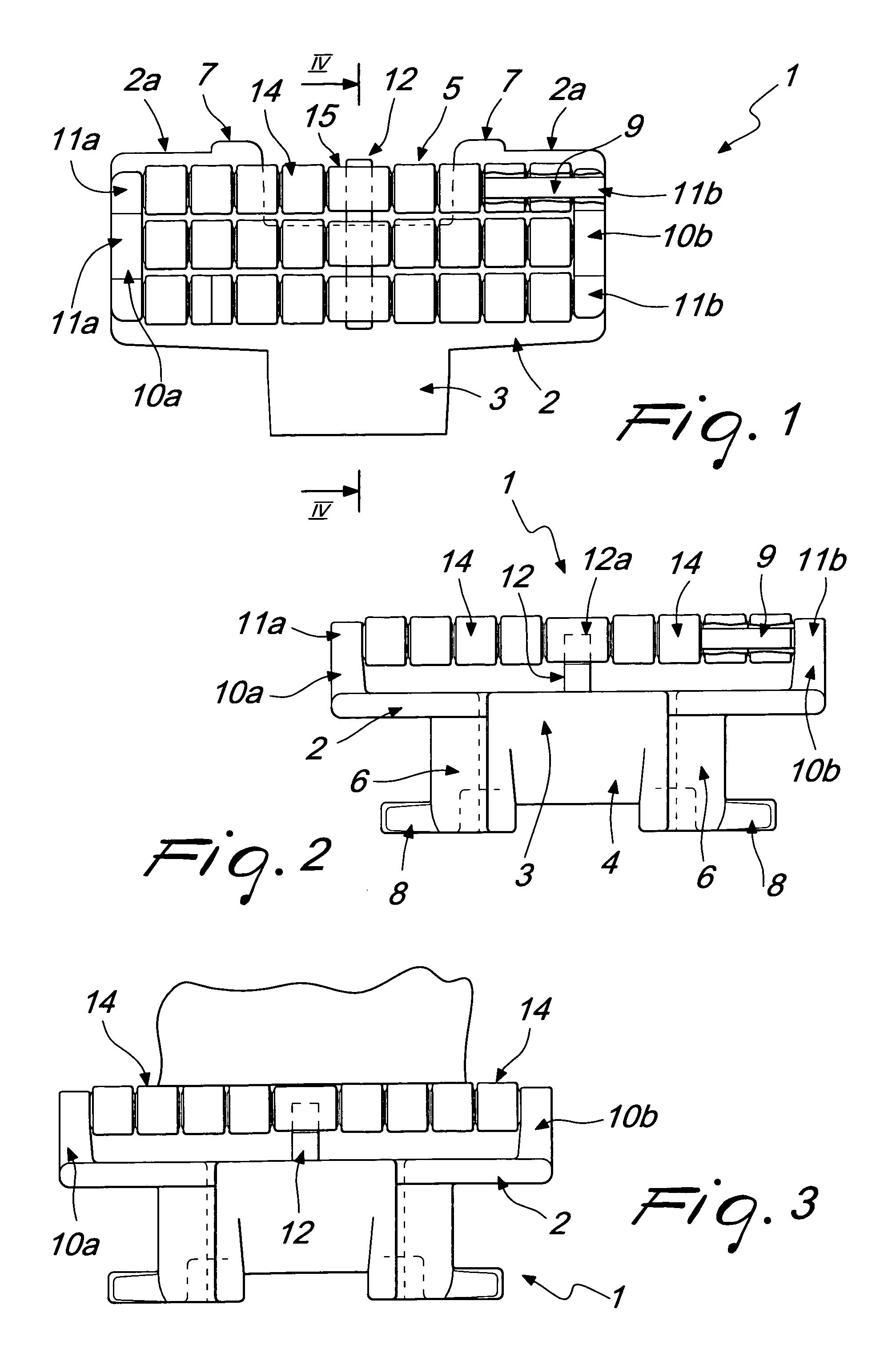
[0035]With reference to the figures, the reference numeral 1 designates a conveyor chain link according to the invention, which is constituted by a main base body 2, which is approximately flat and has an approximately rectangular plan shape.

[0036]Two wings 6 protrude downward from the base body 2 in its central region, are preferably L-shaped, and are arranged symmetrically with respect to a central plane of the link 1.

[0037]The link 1 comprises known connection means for articulated connection to a similar adjacent link, so as to allow to provide a conveyor chain that is constituted by a succession of a plurality of identical links 1 arranged consecutively with respect to each other along the advancement direction of said chain.

[0038]Said connection means for articulated connection are constituted by a lug 3, which is arranged between the wings 6, protrudes frontally and centrally from the main base body 2, has an approximately trapezoidal plan shape and is arranged so that its sh...


PUM


Abstract

A link of a conveyor chain comprising a main base body, a supporting element for supporting and retaining at least one supporting shaft with which a plurality of first rollers are rotatably associated, the link being adapted to be articulated to a similar adjacent link so as to form a conveyor chain.

Description

BACKGROUND OF THE INVENTION[0001]In the production of industrial plants for bottling liquids or for packaging items of various kinds, the design of appropriate systems for transferring the products from one processing station to the next and toward the store is extremely important.[0002]In carrying out the production cycles performed by these plants, it is often necessary to convey and stop the conveyed products in chosen positions, so that it is possible to perform the various steps provided by said process, such as for example filling bottles, closing them, or packaging products of various kinds.[0003]Conveyor chains of a known type are currently used to transfer items within plants in which the operating cycles entail conveying or stopping said products in one or more positions; said known chains are composed of a plurality of links, which are mutually connected so as to form a chosen path, which can comprise straight and curved portions.[0004]One particularly felt requirement is...

Claims


Application Information

Patent Timeline
Patent Type & Authority Patents(United States)
IPC IPC(8): B65G17/24
CPCB65G17/32B65G17/40
Inventor FANDELLA, SERGIO
Owner HABASIT AG
Why Eureka
Try Eureka