
Bicycle towing device

a towing device and bicycle technology, applied in the field of bicycles, can solve the problems of unsafe lifting of the front wheel of the trailing bicycle off the ground, poor overall maneuverability of the arrangement, etc., and achieve the effect of simple, safe and stably towing the trailing bicycle, stable maneuverability and greater control over the maneuvering of the trailing bicycl

Inactive Publication Date: 2007-06-26
GIESE CURTIS FREDERICK
View PDF7 Cites 13 Cited by
  • Summary
  • Abstract
  • Description
  • Claims
  • Application Information

AI Technical Summary

Benefits of technology

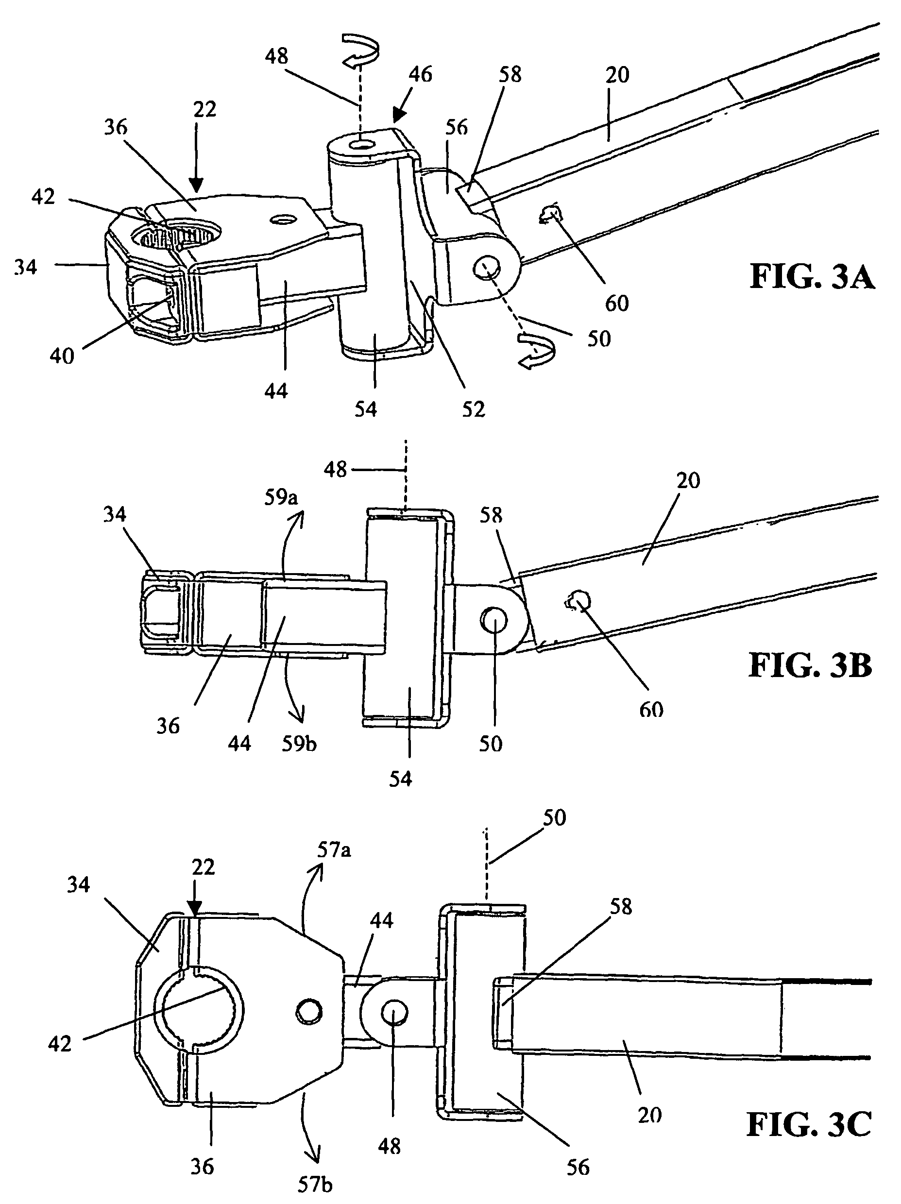
"The present invention is a bicycle towing device that allows for safe and stable towing of a trailing bicycle behind a leading bicycle. The device includes a tow bar that connects to both the leading and trailing bicycles, providing better maneuverability and stability of the trailing bicycle. The connection to the leading bicycle is made through a clamp and two arms that pivot in two directions, allowing for smooth movement. The tow bar is also connected to a pivotal joint on the trailing bicycle connection, which ensures the same angle of lean for the trailing bicycle as the leading bicycle. The technical effects of this invention include improved control and stability of the trailing bicycle, making it easier to maintain a safe distance behind the leading bicycle."

Problems solved by technology

Many previous attempts at bicycle towing devices resulted in arrangements having poor overall maneuverability by providing too flexible of a connection between the bicycles or one that allows the trailing bicycle to steer its front wheel independently from the leading bicycle.
Alternatively, too rigid of a connection between the bicycles by a bicycle towing device can cause the front wheel of the trailing bicycle to be lifted off the ground in an unsafe manner when the leading bicycle and the trailing bicycle are not traveling at the same height, such as when the two bikes pass over bumps or holes in the traveling surface.

Method used


Image

  • Bicycle towing device
  • Bicycle towing device
  • Bicycle towing device

Examples


Embodiment Construction

[0014]The following description is provided to enable any person skilled in the art to make and use the invention and sets forth the best modes contemplated by the inventors of carrying out their invention. Various modifications, however, will remain readily apparent to those skilled in the art, since the general principles of the present invention have been defined herein specifically to provide a multi-purpose combined ladder / cart assembly.

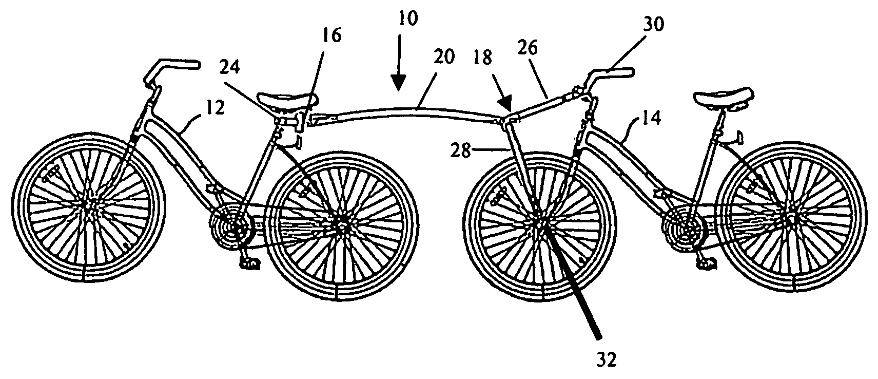
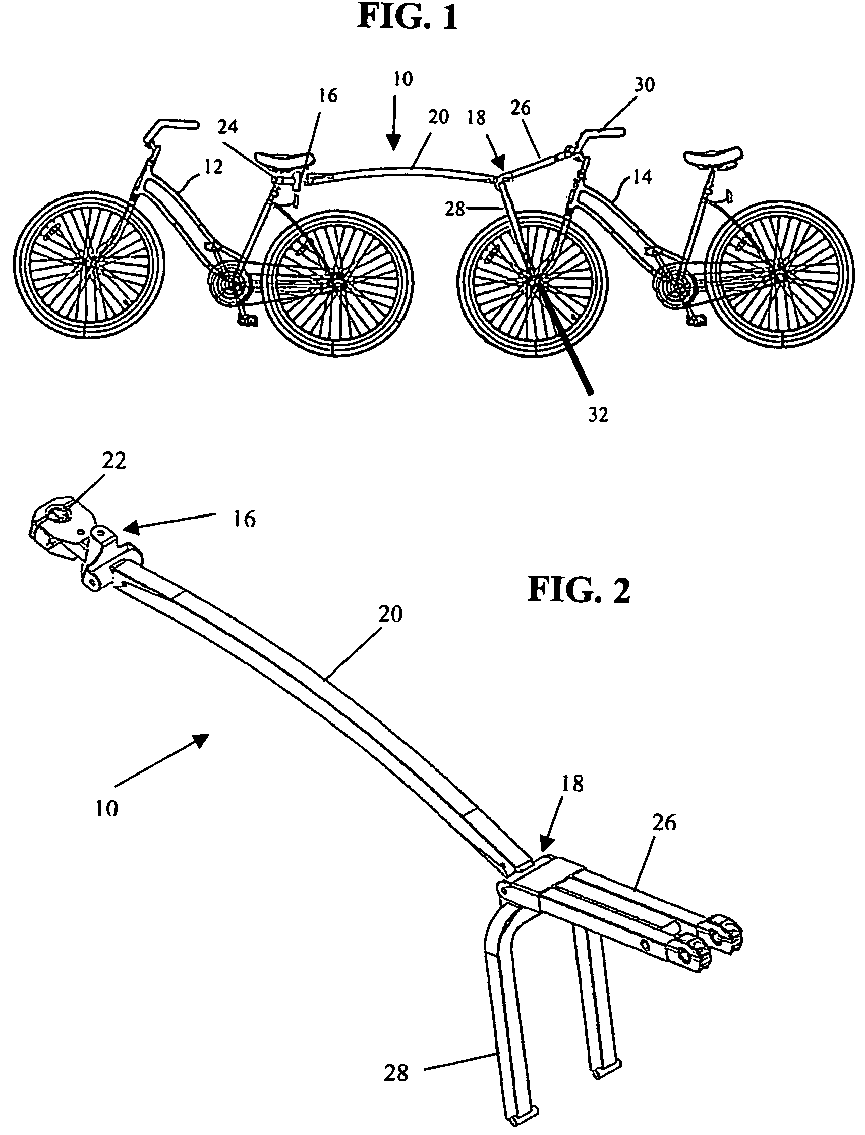
[0015]Referring to FIG. 1, a bicycle towing device 10 formed in accordance with a preferred embodiment is illustrated interconnecting a leading bicycle 12 with a trailing bicycle 14. The bicycle towing device 10 includes a leading bicycle connection 16 connectable to the leading bicycle 12 and a trailing bicycle connection 18 connectable to the trailing bicycle 14. A tow bar 20 connects the leading bicycle connection 16 to the trailing leading bicycle connection 18. In this manner of connection, the bicycle towing device 10 can be utilized to in...


PUM


Abstract

A bicycle towing device for towing a trailing bicycle behind a leading bicycle including a leading bicycle connection interconnected to a trailing bicycle connection by a tow bar. The trailing bicycle connection is connectable to both upper and lower locations on the trailing bicycle such that the center of gravity of the force pulling the trailing bicycle is centered on the trailing bicycle to provide stable maneuverability of the trailing bicycle. The leading bicycle connection and the trailing bicycle connection include pivotal joints that allow limited degrees of rotational movement with respect to the tow bar. In this manner of attachment, the tow bar is pivotal with respect to both the leading bicycle connection and the trailing bicycle connection to account for differences in height between the bicycles while forcing the trailing bicycle to lean at substantially the same exact angle as the leading bicycle at all times.

Description

BACKGROUND OF THE INVENTION[0001]1. Technical Field[0002]The subject invention relates generally to the field of bicycles, and, more particularly, to a device for towing a trailing bicycle behind a leading bicycle.[0003]2. Description of Related Art[0004]It has been known to link two bicycles together to tow a trailing bicycle behind a leading bicycle to form a sort of tandem bicycle arrangement. Such towing arrangements are particularly useful in teaching a child or another person how to ride a bicycle by attaching the child's bicycle to an adult's bicycle and simply towing the child's bicycle behind the riding adult. Such links usually involve attaching a rigid rod or frame between the seat mount member of the forward bicycle and a portion of the front frame of the trailing bicycle. The joined combination then allows the two bicycles to move in unison.[0005]Many previous attempts at bicycle towing devices resulted in arrangements having poor overall maneuverability by providing to...

Claims


Application Information

Patent Timeline
Patent Type & Authority Patents(United States)
IPC IPC(8): B62K27/00B62K13/02B62K27/12
CPCB62K13/02B62K27/12
Inventor GIESE, CURTIS FREDERICK
Owner GIESE CURTIS FREDERICK
Learn More