Locking device

a technology of locking device and lock body, which is applied in the direction of lock applications, carpet fasteners, mechanical apparatus, etc., can solve the problems of difficult to switch the lock member to the opened state, and achieve the effect of removing malfunction and effectively bouncing up the movable member

Inactive Publication Date: 2007-06-26
NIFCO INC
View PDF8 Cites 55 Cited by
  • Summary
  • Abstract
  • Description
  • Claims
  • Application Information

AI Technical Summary

Benefits of technology

[0017]In the present invention, the locking device has the following advantages. The lock member is switched from the locked position to the unlocked position with the rotation of the movable member in the direction opposite to the opening direction. The engaging recess is provided for engaging the lock member, so that the lock member abuts against the corresponding surface of the recess to push or bounce up the movable member in the opening direction through the reactive force, thereby solving the problems.
[0018]The rotation guide device is formed of a small number of parts. The urging member is provided for urging the lock member in addition to the spring member for urging the operating button, thereby eliminating malfunction. The urging member has the first and second urging devices, i.e., the first urging device for urging the lock member toward the locked position and the second urging device for urging the lock member not to rotate inadvertently. It is also possible to effectively bounce up the movable member with the lock member.

Problems solved by technology

Second, the operating button 52 is assembled in the lock member 53 such that the sliding section 52b is inserted into the coupling hole 53c and the slanted end faces abut against each other. Accordingly, dust or the like may accumulate, for example, between the slanted end faces. In this case, when the pressure is removed, the lock member 53 may not return to the original projected position or the locked position smoothly. Further, the lock member 53 may vibrate or move up and down, thereby causing malfunction.
Third, an elastic member may be disposed at a portion where the body abuts against the cover for absorbing an impact or preventing rattle. In such a case, when the cover is closed for a prolonged period of time, the elastic member may deform and deteriorate, thereby sticking the body and the cover together. Accordingly, even if the operating button is pressed to switch the lock member to the unlocked position, it is difficult to switch the lock member to the opened state.

Method used


Image

  • Locking device
  • Locking device
  • Locking device

Examples


Embodiment Construction

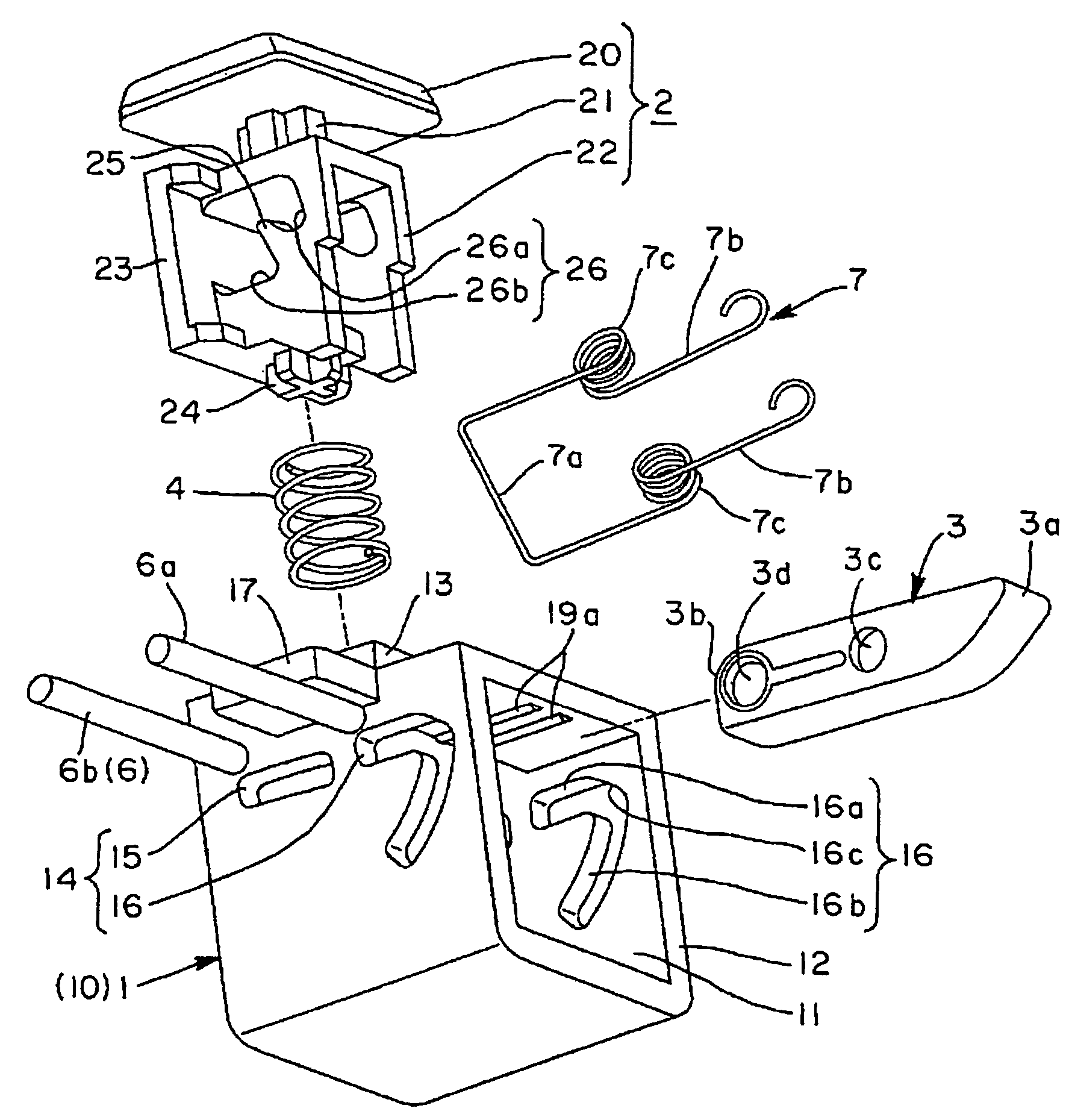
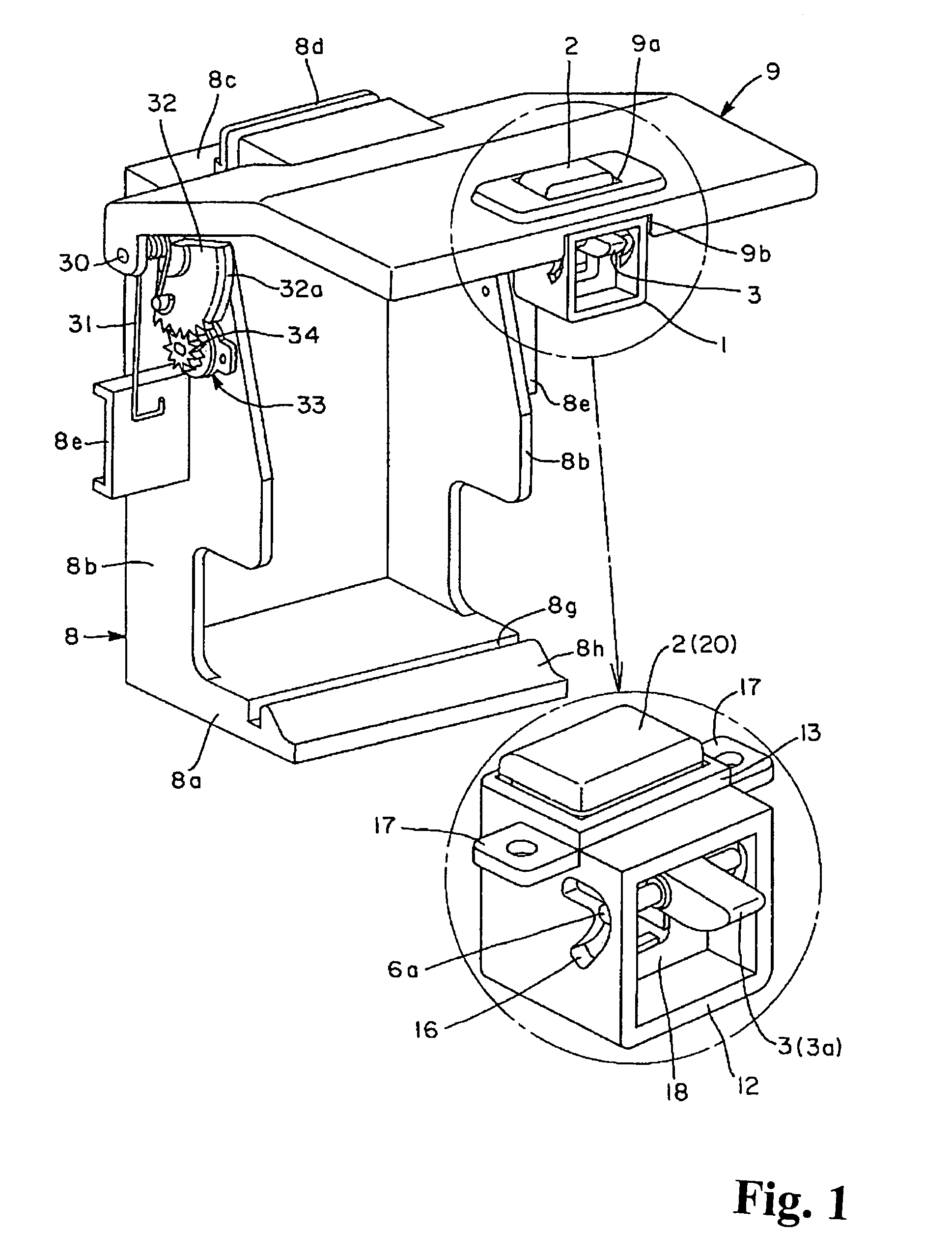
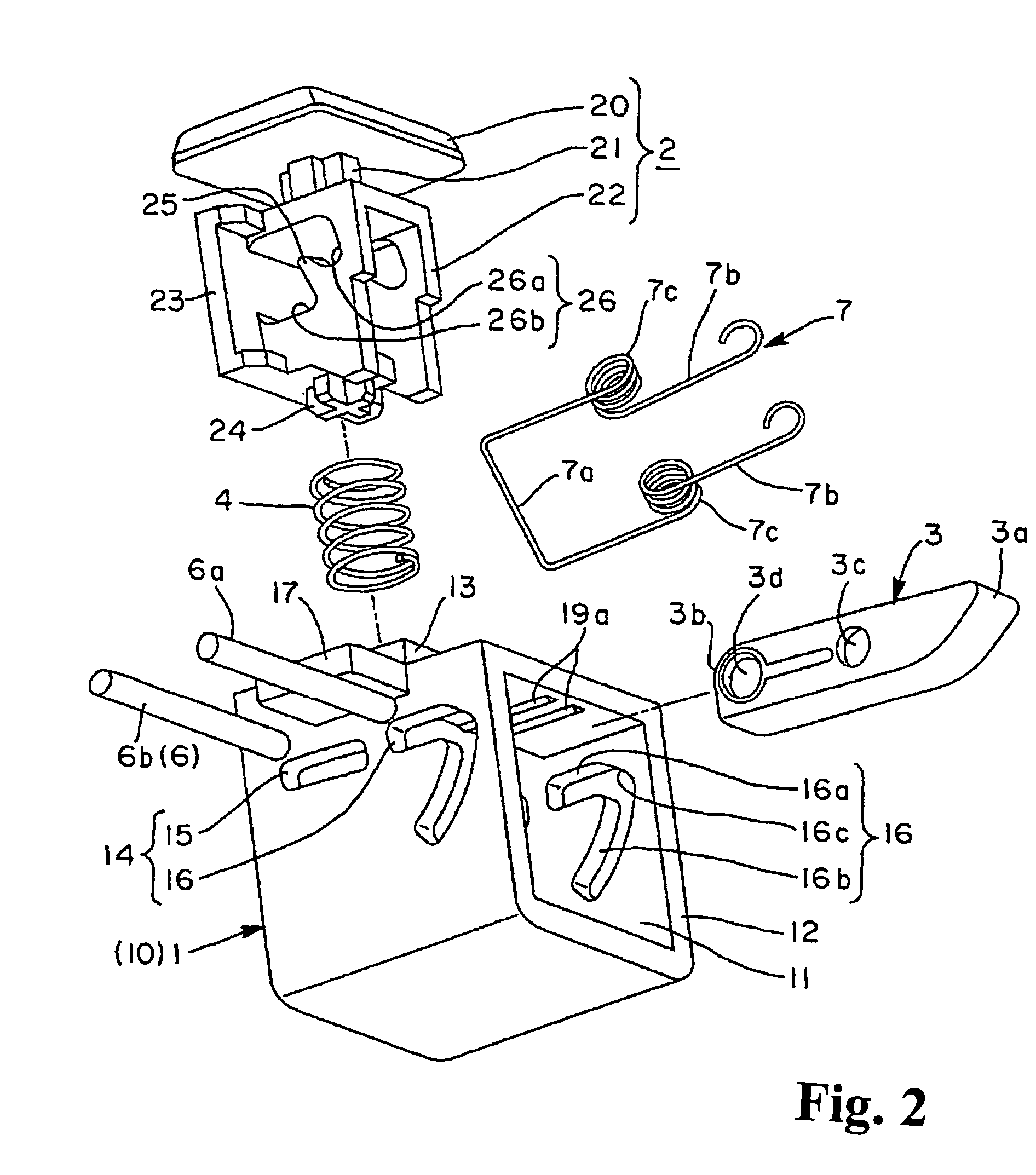
[0027]Hereunder, embodiments of the present invention will be explained with reference to the accompanying drawings. FIG. 1 is a schematic illustration of one example of the locking device according to the present invention applied to an appliance, and FIG. 2 is an exploded view showing the construction of the locking device. FIGS. 3(a), 3(b), 4(a) and 4(b) illustrate the locking device in the locked position and the initial position of unlocking (the bounced up position). FIGS. 3(a) and 4(a) are views of the lock member from the side out of which it projects, and FIGS. 3(b) and 4(b) are sectional views taken along lines 3(b)-3(b) and 4(b)-4(b), respectively. In the following explanation, the invention will be described in the order of summary, construction of the pertinent sections, assembly, and operation.

(Summary)

[0028]The locking device in this embodiment includes an operating button 2 and a lock member 3 that are placed in relation with one another within a case 1, and is of th...


PUM


Abstract

A locking device includes an operating button and a lock member disposed in a case. When the operating button is pressed against an urging force of a spring member, the lock member switches from a locked position for restricting a movable member to move relative to a body to an unlocked position for allowing the movable member to move in an opening direction. A rotation guide device is disposed between the case and the operating button, so that the lock member switches from the locked position to the unlocked position when the movable member rotates in a direction opposite to the opening direction.

Description

BACKGROUND OF THE INVENTION AND RELATED ART STATEMENT[0001]The present invention relates to a locking device for locking a movable member such as a cover to a body in a closed state, and more particularly, relates to a locking device for unlocking a movable member through pressing an operating button.[0002]A locking device shown in FIGS. 8(a) and 8(b) is disclosed in Patent Reference 1. The locking device includes an operating button 52 and a lock member 53 disposed in a case 51. When the operating button 52 is pressed against an urging force of a spring member 54, the lock member 53 switches from a locked position for restricting a cover 61 to rotate relative to a storage body 60 (refers to as a locked state) to an unlocked position for allowing the cover 61 to rotate in an opening direction (refers to an unlocked state).[0003]The case 51 is formed of a recess portion including an open portion of the storage body 60, and slide slots 51a and 51b are formed in opposing walls of the r...

Claims


Application Information

Patent Timeline
Patent Type & Authority Patents(United States)
IPC IPC(8): E05C1/12E05C1/08E05C3/22
CPCE05C5/00E05C1/14Y10S292/37Y10T292/0886Y10T292/0976E05C3/22E05B83/18
Inventor HARADA, AKINORI
Owner NIFCO INC
Why Eureka
Try Eureka