Device for retracting tissue

a tissue retractor and tissue technology, applied in the field of tissue retractor devices, can solve the problems of cumbersome adjustment of the desired retraction position of the tissue to be retracted, and achieve the effects of reducing the cross section of the cutout reducing the ability of the retaining element, and improving the handling ability of the retractor device according to the invention

Inactive Publication Date: 2007-06-26
MAX HAUSER SUDDEUTE CHIRURGIEMECHANIK
View PDF12 Cites 73 Cited by
  • Summary
  • Abstract
  • Description
  • Claims
  • Application Information

AI Technical Summary

Benefits of technology

[0041]An additional, particularly preferred embodiment of the invention provides that the clamping sleeve comprises a slot running essentially parallel to the axis of rotation, in which a pin arranged on the clamping part is guided. By virtue of this characteristic of the invention, twisting of the clamping sleeve about the first axis of rotation relative to the clamping part is suppressed, so that the cross section of the cutout of the retaining element is not reduced by twisting of the clamping sleeve relative to the clamping part, which would have the result that the retractor arm could no longer be inserted into the cutout of the retaining element.
[0042]To limit the ability of the retaining element to twist about the first axis of rotation relative to the bearing block, a preferred embodiment provides that a pin that is actively connected to a slot in the retaining element is arranged on the bearing block, so that a rotational motion of the retaining element about the first axis of rotation relative to the bearing block is possible only within a given angular range. The handling ability of the retractor device according to the invention is considerably improved by this characteristic of the invention as well, since, in the unfixed state, it suppresses twisting of the retaining element into a position in which, for instance, the cutout is arranged such that insertion of the retractor rod would be impossible for the surgeon.
[0043]Another particularly preferred embodiment provides that the slide part can be displaced infinitely variably along a slide rod. This defines an additional degree of freedom for the blades because the slide part can be displaced relative to a slide rod.

Problems solved by technology

This has the disadvantage that the adjustment of the desired retraction position of the tissue to be retracted is often cumbersome and is done with too little feeling.

Method used


Image

  • Device for retracting tissue
  • Device for retracting tissue
  • Device for retracting tissue

Examples


Embodiment Construction

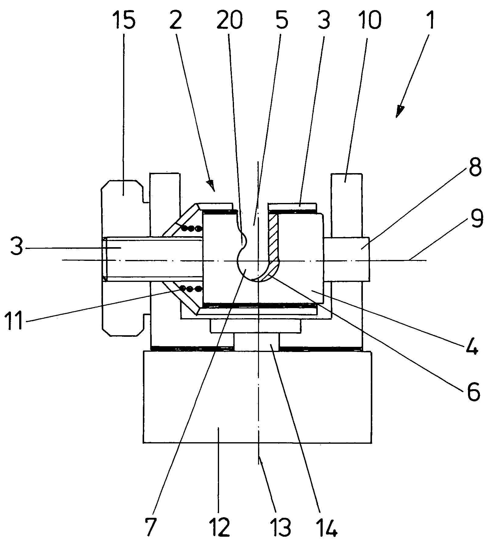
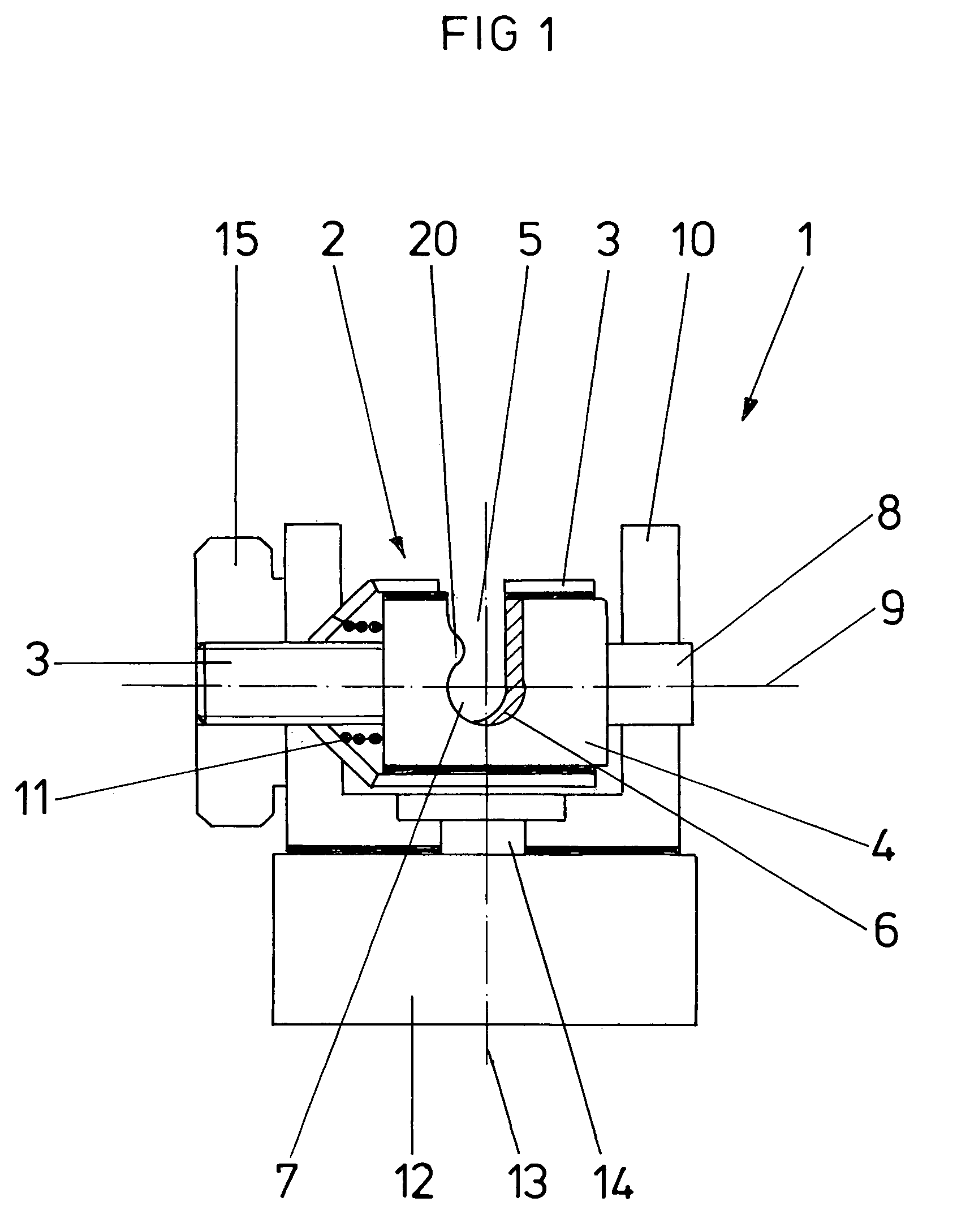
[0053]FIG. 1 shows a device 1 according to the invention for retracting tissue in cross section with the retractor arm not inserted.

[0054]Device 1 for retracting tissue comprises a retaining element 2 with a clamping sleeve 3 and a clamping part 4 movably guided in clamping sleeve 3. Clamping sleeve 3 has a U-shaped cross section, by virtue of which a cutout 5 is formed in clamping sleeve 3 and a cutout 6 in clamping sleeve 4. In this case, each of the two cutouts 5 and 6 opens upwards in the representation of FIG. 1, the openings pointing in the same direction. Cutouts 5 and 6 extend continuously through clamping sleeve 3 and clamping part 4, respectively, so that a continuous cutout 7 of retaining element 2 with a groove shape is formed in the overlap area of the two cutouts 5 and 6. A retractor arm holding a blade in place can be inserted from above into groove-shaped cutout 7. A catch bead on clamping part 4 running in the direction of cutouts 5, 6 and 7 is provided to secure an...


PUM


Abstract

A device (1) for retracting tissue with a retaining element (2) with a throughgoing cutout (7) and with a blade (18) mounted on a retractor arm (16), retractor arm (16) being seated movably in cutout (7), wherein cutout (7) of retaining element (2) is formed in a groove shape.

Description

FIELD OF THE INVENTION[0001]The present invention pertains to a device for retracting tissue and other parts of the body during surgical interventions according to the preamble of Claim 1.BACKGROUND OF THE INVENTION[0002]A device of this class for retracting tissue comprises as a rule a retaining element with a throughgoing cutout, as well as a blade fastened on a retractor arm. In this case, the rod is seated movably in the cutout of the retaining element and can be fixed in place by means of a locking element in a desired position on the retaining element.[0003]DE 199 23 534 C1 discloses a retractor unit with several blades, each arranged on a retractor arm. The retractor arms are arranged along a straight rod so as to be movable and lockable thereon. Each retractor arm is connected to the rod via a connecting element referred to as a rack box, said rack box comprising two hole-like cutouts running perpendicular to one another and extending through the rack box. The rod is guided ...

Claims


Application Information

Patent Timeline
Patent Type & Authority Patents(United States)
IPC IPC(8): A61B1/32A61B17/02
CPCA61B17/02
Inventor REIN, JOACHIMHEMMER, WOLFGANGKUPKA, THOMAS F.REHM, WALTER
Owner MAX HAUSER SUDDEUTE CHIRURGIEMECHANIK
Why Eureka
Try Eureka