Method and vertical mill for grinding a product to be milled

A grinding machine, a technology to be ground, applied in the direction of grain processing, etc., can solve the problems of high pressure loss, increased pressure loss, burden, etc., to achieve the effect of reducing the overall burden, reducing pressure loss, and improving pneumatic conveying

Inactive Publication Date: 2015-05-20
LOESCHE GMBH
View PDF6 Cites 5 Cited by
  • Summary
  • Abstract
  • Description
  • Claims
  • Application Information

AI Technical Summary

Problems solved by technology

[0009] However, this flow pattern leads to a considerable loss of the operating output of the vertical mill, since firstly small fine particles enter the annular gap 21 with the pressure drop or respectively with the gas suction due to their lower mass
Small particles of the material to be ground introduced in this way into the annular gap 21 not only unnecessarily burden the grinding material circuit of the vertical grinding machine and thus increase the resulting pressure loss, but they also endanger the grinding table Mutual cooperation of the grinding bed on the as well as load behavior, which leads to an increased vibration tendency
[0010] As a result of these problems and the associated disadvantages which grow with the size of vertical mills, which manifest themselves as high pressure losses within the vertical mill, high operating vibrations of the grinding rollers and consequently impaired operating efficiency of the vertical mill These problems must be overcome in the form of

Method used


Image

  • Method and vertical mill for grinding a product to be milled
  • Method and vertical mill for grinding a product to be milled
  • Method and vertical mill for grinding a product to be milled

Examples


Embodiment Construction

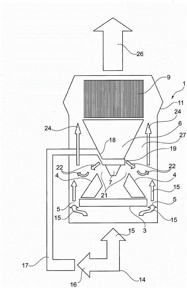
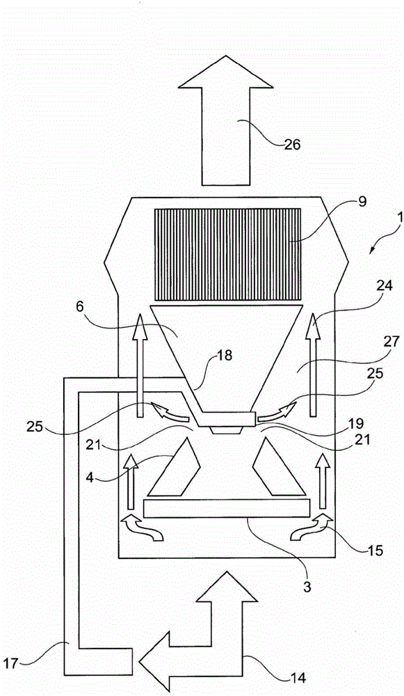
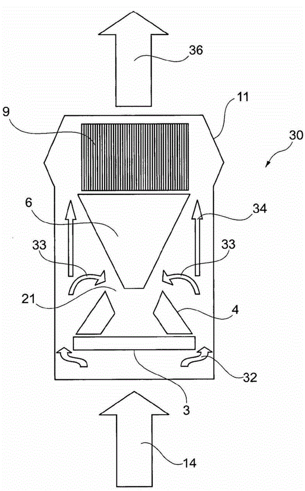
[0045] figure 1 , figure 2 and image 3 The main components of the vertical mills shown in are all of the same construction, such as the grinding table 3, the grinding rollers 4, the oversized material cone 6 and the classifier 9 arranged above and the surrounding mill housing Body 11.

[0046] Problematic recirculation flow 33 ( image 3 ) and its diversion into the annular gap 21, can be constructed in a simple manner and by according to figure 1 and figure 2 The solution method to overcome.

[0047] in accordance with figure 1 In the embodiment of the vertical grinding machine 1, a part of the air flow is diverted from the main air flow 14 via the branch line 17.

[0048] When the grinding process carried out in the vertical grinding mill is a grinding-drying process (for example for moist raw coal), hot air is generated in the hot gas generator and fed as main air flow 14 below the grinding table 3 to the vertical grinding mill. Grinder 1. A part of the air flo...


PUM


Abstract

The invention relates to a vertical mill for grinding a product to be milled and a method therefor, wherein the vertical mill has a grinding plate and one or more grinding rolls. A blade ring annular channel is provided for a transport gas flow rising around the grinding plate. An annular gap is provided between a downwards projecting middlings cone and the upper range of the grinding rollers through which gap even a fines content is recirculated back to the grinding plate. To overcome this disadvantage, a barrier gas flow is provided flowing from the inside towards the outside, by means of which the recirculation of ground particles of a defined size can be prevented.

Description

technical field [0001] The invention relates to a method for grinding material to be ground in a vertical grinder according to the preamble of claim 8 and to a vertical grinder according to the preamble of claim 1 . Background technique [0002] A vertical grinding machine according to the preamble of claim 1 is known, for example, from EP 1 675 683 B1 and is illustrated schematically in image 3 Its main components are shown in . [0003] This vertical grinder has a rotating grinding table 3 on which grinding rollers 4 or grinding mills are arranged to crush and grind the material to be ground, which is fed into the central area of ​​the grinding disc 3, such as cement raw materials or raw coal. [0004] Depending on the type of material to be ground that is fed to the grinding disc 3 , the main air stream 14 , which is usually a hot air stream in the grinding-drying process, passes through the vertical grinder 30 from the bottom up. Hot air blown in from the bottom, use...

Claims


Application Information

Patent Timeline
Patent Type & Authority Applications(China)
IPC IPC(8): B02C15/04B02C23/12
CPCB02C23/12B02C15/001B02C15/04
Inventor 马蒂亚斯·默斯曼
Owner LOESCHE GMBH
Why Eureka
Try Eureka