Eureka AIR delivers breakthrough ideas for toughest innovation challenges, trusted by R&D personnel around the world.

Process And Apparatus For Producing Olefin Polymers

a technology of olefin polymerization and process, applied in the field of olefin polymerisation, can solve the problems of unsatisfactory polymerization methods or apparatus, present methods for concentrating the polymer slurry of a loop reactor,

Active Publication Date: 2008-02-14
BOREALIS TECH OY
View PDF1 Cites 10 Cited by
  • Summary
  • Abstract
  • Description
  • Claims
  • Application Information

AI Technical Summary

Benefits of technology

[0010] It is an aim of the present invention to eliminate disadvantages of the prior art and to provide a novel and economical process for producing olefin, in particular ethylene, homopolymers and copolymers.
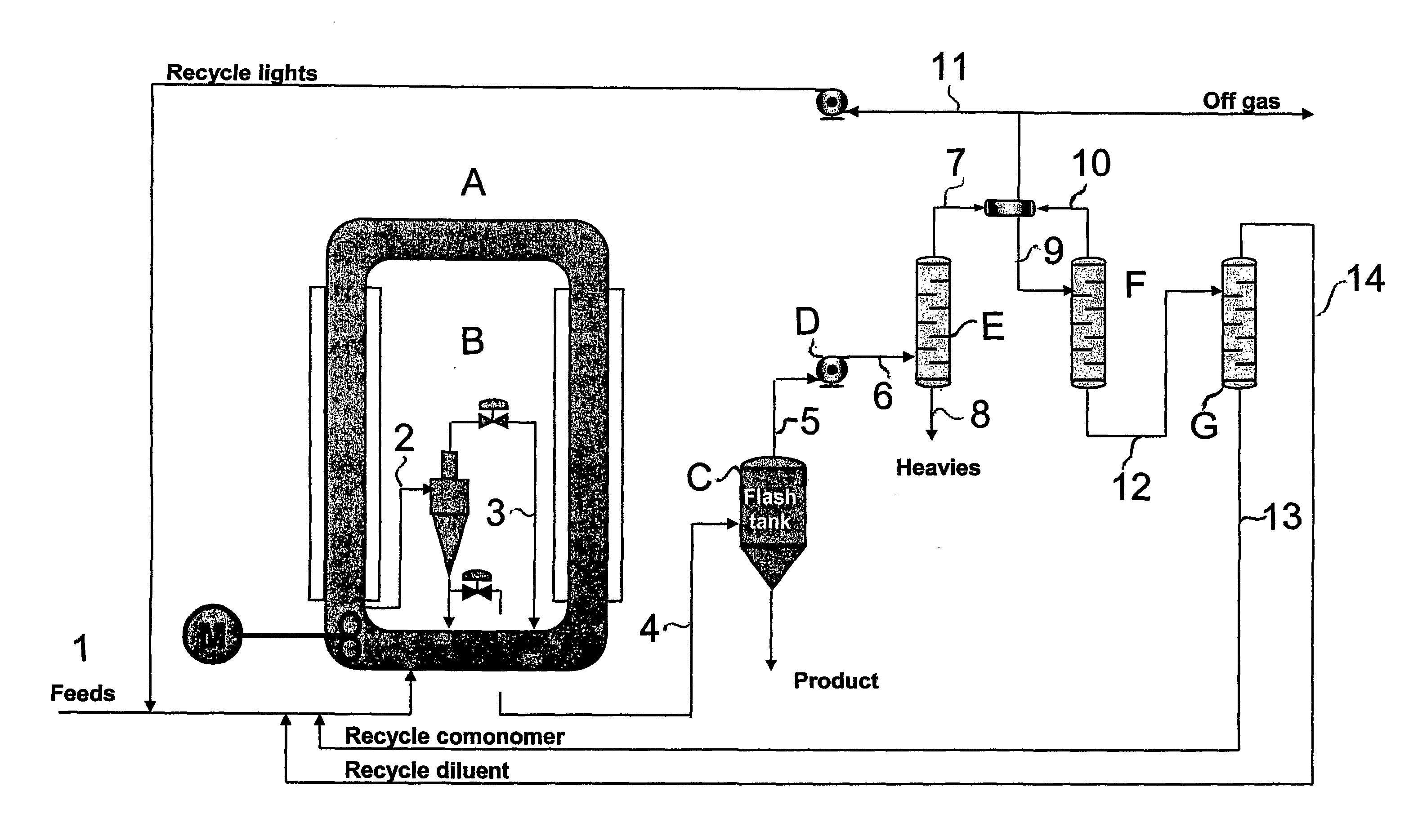
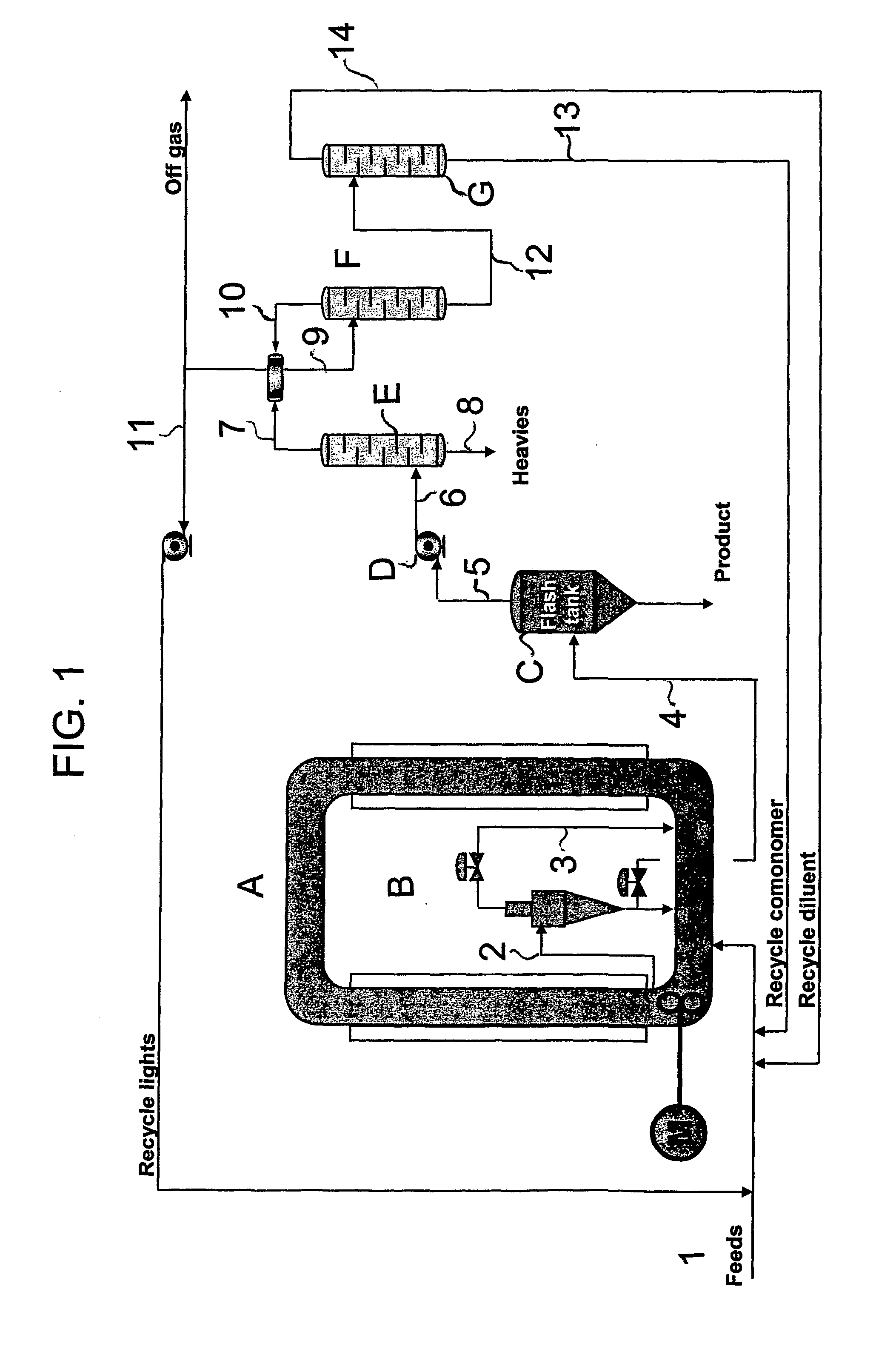
[0011] The invention is based on the idea of essentially increasing the concentration of the polymer slurry before a flash unit so as to reduce the gas flow from the flash to a subsequent flash gas compressor. The effluent streams of the gas compressor are, as known per se, conducted to a separation zone, such as a distillation section comprising heavies column(s) and lights column(s). By means of the invention it is possible significantly to reduce the capacity and size of the gas compressor and of the subsequent distillation section.
[0027] The present invention provides important advantages. By means of the invention, an economical process can be achieved, since the size of the flash gas compressor can be reduced. Without the hydrocyclone the flash gas stream would include, in addition to the flash gas stream of the present examples, also 50% of the overhead stream from the hydrocyclone. Thus, the flash gas stream would be larger. Because the streams are smaller, the size of the separation units can be reduced. The invention provides for a smaller heavies column, lights column and comonomer column. Smaller process equipment means smaller investment costs. Savings in the operation and running costs of the process can also be achieved. The energy consumption is reduced since recycle gas flows are smaller. This also means a more economical and environmentally friendly process.

Problems solved by technology

However, present methods for concentrating the polymer slurry of a loop reactor have been unsatisfactory.
Even if the above documents describe different methods of withdrawing the slurry from the loop reactor, none of them discloses or suggests a polymerization method or apparatus, where the size of the separation units can be kept small compared to the product flows.

Method used


Image

  • Process And Apparatus For Producing Olefin Polymers
  • Process And Apparatus For Producing Olefin Polymers

Examples


example 1

[0064] A 10 m3 loop reactor is operated at 95° C. and 60 bar pressure with propane diluent. Ethylene homopolymer is produced in the reactor by introducing ethylene, diluent, hydrogen and a polymerisation catalyst, which was prepared according to Example 3 of EP 688794 with the exception that as a carrier material silica having an average particle size of 20 μm is used, in such quantities that the diluent contains 5.9 mol-% of ethylene and 2.6 mol-% hydrogen. The remainder is propane with minor quantities (less than 1 mol-% each) of methane, ethane, isobutane and n-butane. The polymer production is 1.4 tons per hour; the melt index of the polymer is 450 g / 10 min and the density 973 kg / m3 The solids content of the slurry is 25 vol-%.

[0065] The polymer slurry is withdrawn continuously from the reactor through an outlet nozzle and transferred to a hydrocyclone according to FIG. 1. The total slurry feed to the hydrocyclone is 5.5 tons per hour. The product flow is 3.7 tons per hour, wit...

example 2

[0069] Into the reactor of Example 1 is introduced ethylene, 1-butene, hydrogen and diluent, as well as similar catalyst to what was used in Example 1, so that the reaction mixture contains 6.8 mol-% ethylene, 3.1 mol-% 1-butene and 1.8 mol-% hydrogen. Polymerisation temperature is 85° C. The polymer production is 1.2 tons per hour, the melt index of the polymer is 200 g / 10 min and the density 950 kg / m3. The solids content of the slurry is 25 vol-%.

[0070] The polymer slurry is withdrawn continuously from the reactor through an outlet nozzle and transferred to a hydrocyclone according to FIG. 1. The total, slurry feed to the hydrocyclone is 5.2 tons per hour. The product flow is 3.8 tons per hour, with 39 vol-% of solids. The recycle flow is 1.4 tons per hour, with 5.8 vol-% solids. The recycle flow is returned to the loop reactor. The product flow is divided into two streams: The product withdrawal stream is about 1.9 tons per hour and the product recycle stream about 1.8 tons per ...


PUM

PropertyMeasurementUnit
Fractionaaaaaaaaaa
Timeaaaaaaaaaa
Fractionaaaaaaaaaa

Abstract

The present invention concerns a process and an apparatus for continuous polymerisation of olefin monomers. In particular, the present invention concerns a process and an apparatus for continuous polymerisation olefin monomers like ethylene and other monomers, wherein an olefin monomer is polymerised in slurry phase in an inert hydrocarbon diluent in at least one loop reactor. According to the invention, a polymer slurry is continuously withdrawn from the loop reactor and concentrated. The concentrated slurry is conducted to a flash unit in order to remove the remaining fluid phase, and gas obtained is compressed in a flash gas compressor before it is being fed to a distillation section. By means of the present invention it is possible reduce the size of the flash gas compressor and the capacity of the distillation sections. This significantly reduces investment cost for a continuously operated polymerization apparatus.

Description

BACKGROUND OF THE INVENTION [0001] 1. Field of the Invention [0002] The present invention relates to olefin polymerisation. In particular, the present invention concerns a process and an apparatus for continuous polymerisation olefin monomers like ethylene and other monomers, wherein an olefin monomer is polymerised in slurry phase in an inert hydrocarbon diluent in at least one loop reactor. [0003] 2. Description of Related Art [0004] The loop reactor was developed in the 1950's. It is now widely used for the production of polyethylene and other olefin polymers. In a loop reactor, ethylene is polymerised in the presence of a hydrocarbon diluent in slurry phase at elevated pressure and temperature. The slurry is withdrawn from the reactor and concentrated so that the solids content at the reactor outlet is higher than the solids content in the reactor. Traditionally, this has been done by using settling legs. However, present methods for concentrating the polymer slurry of a loop re...

Claims


Application Information

Patent Timeline
IPC IPC(8): C08J11/04B01J19/00B01J8/00B01J8/20B01J19/18C08F6/00C08F6/20C08F10/00C08F10/02C08F110/02C08F210/16
CPCB01J8/0015B01J19/1837C08F210/16C08F110/02C08F10/02C08F6/20C08F6/003B01J2219/00006B01J2208/00761B01J2208/00274B01J2208/003C08L23/04C08F2/14C08F210/08
Inventor VUORIKARI, MARIANNAKORHONEN, ESAANDTSJO, HENRIKZITTING, SAMULI
Owner BOREALIS TECH OY
Why Eureka
Eureka Blog
Learn More