Air bag inflation exit gas dispersion features

a technology of airbags and gas dispersion, which is applied in the direction of pedestrian/occupant safety arrangements, vehicular safety arrangements, vehicle components, etc., can solve the problems of concentrated streams of gas scorching burning through the airbag cushion, and damage to the inside surface of the airbag cushion. , to achieve the effect of not increasing the thickness of the airbag cushion

Inactive Publication Date: 2002-05-28
AUTOLIV ASP INC
View PDF6 Cites 9 Cited by
  • Summary
  • Abstract
  • Description
  • Claims
  • Application Information

AI Technical Summary

Benefits of technology

It is an object of the present invention to protect the inside surface of the air bag cushion from the concentrated streams of gases produced during deployment of the air bag cushion without increasing the thickness of the air bag cushion.
FIGS. 6 and 7 depict another embodiment of apertures 70 formed through side wall 18 diffuser canister 14. As depicted, apertures 70 are "star-shaped". Unlike apertures 26 and 60 illustrated in FIGS. 1-5, apertures 70 are defined by an edge 72 that is substantially perpendicular to the exterior surface 40. The non-smooth configuration of apertures 70 creates turbulence in the stream of gas that is flowing out of apertures 70 which reduces the concentration of the gas and helps reduce the temperature of the stream of gas flowing out of apertures 70. Although apertures 70 are depicted as star-shaped, apertures 70 can have various other shapes as long as the periphery defined by edge 72 is non-smooth and irregular. By way of example and not limitation, other non-smooth shapes include any scalloped-shaped opening.

Problems solved by technology

This is particularly problematic for the portions of the inside surface of the air bag cushion that are proximate to the apertures formed in the diffuser canister through which the gases exit the diffuser canister and gas generation inflator and enter the air bag cushion.
The concentrated stream of gas exits the diffuser canister so quickly at such a high pressure and with such force that the inside surface of the air bag cushion is damaged.
When the reaction occurring in the gas generation module creates hot gases, the concentrated streams of gas scorch the inside surface of the air bag cushion and may even burn through the air bag cushion.
If a more energetic deployment takes place, the hot gases generated by the gas generation inflator can structurally affect the air bag cushion.
Designers of the air bag assemblies have been limited in what type of reactions can be used to deploy the air bag cushion by the temperature and / or pressure of the gases exiting the diffuser canister that can withstand the air bag cushion.
This inner bag limits the design of air bag cushions as well as the size that the module can be reduced to.
Adding additional layers or linings to portions of the air bag cushion increases the manufacturing steps, the manufacturing time, and the cost of the air bag cushion itself Additional layers, of even just the synthetic material that the air bag cushion is usually made up of, also increases the amount of space that the stored air bag will require, and becomes a limiting factor when trying to reduce the size of the module.
Both of these methods, however, required the use of additional pieces in the air bag assembly.
It was particularly difficult, when assembling the diffuser canister and the air bag cushion to insure that the fabric shield was in the right position to intersect the concentrated flow of gases.
Both of these deflectors, as well as similar methods, also limited how small the air bag assembly module could be made.

Method used


Image

  • Air bag inflation exit gas dispersion features
  • Air bag inflation exit gas dispersion features
  • Air bag inflation exit gas dispersion features

Examples


example 2

Discussion and Conclusion

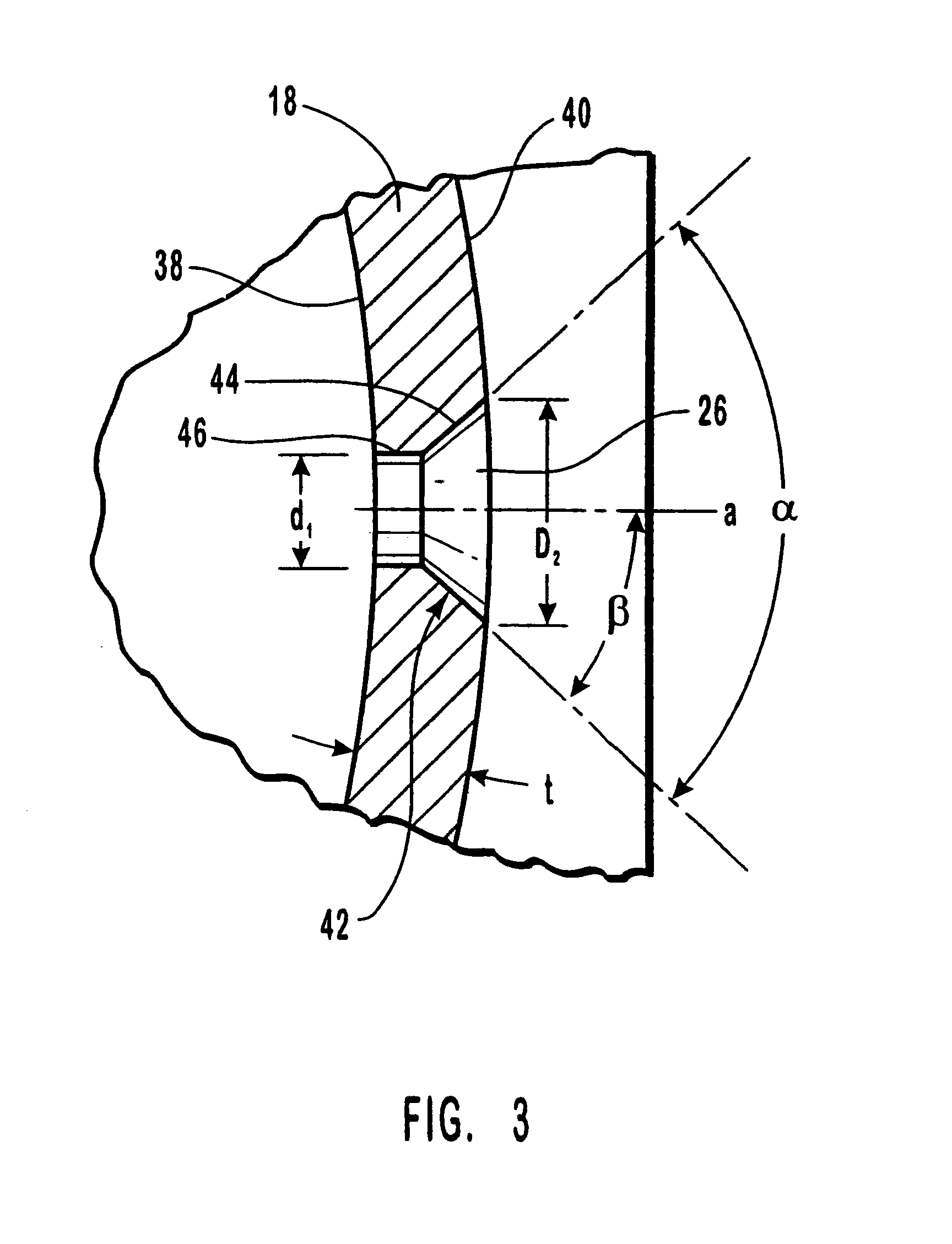
A ratio of diameter d.sub.1 to wall thickness t of 0.96 and 1.2 was used in this test. Adding the countersink to the apertures helped to disperse the gas stream from each aperture. Diffusing the gas reduced the concentration of the stream of gas and helped to reduce the temperature and the pressure of the gas impacting upon the inside surface of the air bag cushion. Approximately a 50% reduction in the number of burned through location in the throat or gas inlet opening of the air bag cushion proximate to the retaining ring were observed.

example 3

TABLE 4

Discussion and Conclusion

Table 3 depicts the equipment and specifications used in Experiment 3. Table 4 depicts the standards used for a baseline comparison. A ratio of diameter d.sub.1 to wall thickness t of 1.67, 2.14, and 2.27 were used in this test. Adding the countersink to the apertures helped to disperse the gas stream from each aperture. Diffusing the gas reduced the concentration of the stream and helped to reduce the temperature and the pressure of the gas impacting upon the inside surface of the air bag cushion. In this experiment, the width of the flat portion proximate to the diameter d.sub.1 was reduced in comparison the that in Experiment 1 and 2. In addition, in this experiment there were three sizes of apertures instead of only two sizes.

A baseline run resulted in two (2) locations of burn through of the air bag cushion. In contrast, the configuration used in the experimental run of Experiment 3 resulted in no cushion burn through. The baseline run indicated ...


PUM


Abstract

An air bag device that includes an air bag cushion, a diffuser canister, and a gas generation inflator. The diffuser canister is attached to the air bag cushion and has walls configured to define an interior space therein. The walls of the diffuser canister have an interior surface, an exterior surface, and a wall thickness t. At least one of the walls has an aperture formed therethrough in communication with the interior of the air bag cushion. The gas generation inflator is configured to rapidly create a gas that exits the diffuser canister through the aperture so as to fill the air bag cushion. The aperture is defined by an edge extending between the interior and said exterior surfaces of the wall that is configured to diffuse the gas exiting the diffuser canister through the aperture. The edge of the aperture is configured such that the cross-sectional area of the aperture that is proximate to the exterior surface of the wall is larger than the cross-sectional area of the aperture proximate to the interior surface of wall. The edge includes an angled portion configured such that opposing sides of the aperture have an angle alpha therebetween in the range of about 20 degrees to about 145 degrees. The aperture has a diameter d1 proximate to the interior surface of the wall and is configured so that the diameter d1 and wall thickness t have a ratio d1 to tin the range of about 0.5 to about 4. An alternate embodiment of the air bag device comprises an aperture defined by an edge that is configured so that the cross-section of aperture is non-smooth and causes turbulence in the gas stream.

Description

1. The Field of the InventionThe present invention relates to a safety device used particularly in automobiles which, upon the onset of a collision, deploys an inflatable restraint cushion, known as an air bag cushion, to protect the occupants of the vehicle from the impact of the collision. More particularly, this invention relates to an apparatus for protecting the inside surface of an air bag cushion from the hot concentrated gases generated during the deployment of the air bag cushion.2. The Relevant TechnologyAn air bag assembly typically includes a diffuser canister that encloses or is attached to a gas generator commonly known as an inflator, at least part of an air bag cushion, and may include a cover which conceals the air bag assembly from view. The air bag assembly is often considered as a module, and the industry is constantly trying to reduce the size of the air bag assembly.When the vehicle, usually an automobile, is involved in a collision, a crash signal actuates the...

Claims


Application Information

Patent Timeline
Patent Type & Authority Patents(United States)
IPC IPC(8): B60R21/26B60R21/20B60R21/217B60R21/261B60R21/264
CPCB60R21/261B60R21/26B60R21/217B60R21/2644
Inventor SODERQUIST, QUINJORDAN, MICHAEL P.HOCK, CHRISTOPHER
Owner AUTOLIV ASP INC
Why Eureka
Try Eureka