Stirling engine, and stirling refrigerator

a technology of stirling refrigerator and stirling engine, which is applied in the field of stirling engines, can solve the problems of reducing the reliability of operation of stirling engines, reducing capability, and reducing miscellaneous losses, so as to reduce internal space, reduce manufacturing costs, and reduce internal space. the effect of capacity

Inactive Publication Date: 2005-09-20
SHARP KK
View PDF21 Cites 11 Cited by
  • Summary
  • Abstract
  • Description
  • Claims
  • Application Information

AI Technical Summary

Benefits of technology

[0094]In the aforementioned fourth invention, the aforementioned lightweight internal member preferably contains either plastic or rubber. The capacity of the internal space can be reduced while keeping the outer shell 0 thin and keeping the internal space large due to employment of this structure. Further, the manufacturing cost can also be inhibited from increase.
[0095]In the aforementioned fourth invention, the specific heat of the aforementioned lightweight internal member is preferably at least 1 kJ / kg·K. The lightweight internal member serves to buffer heat conduction between a low temperature on the working space side and a relatively high temperature on the driving space side due to employment of this structure. Therefore, it is possible to prevent low-temperature working gas, flowing from the compression space into the internal space, from abrupt expansion resulting from temperature increase. Further, the capacity of the internal space is reduced due to arrangement of the lightweight internal member. Consequently, the quantity of miscellaneous loss can be reduced.
[0096]In the aforementioned fourth invention, the aforementioned lightweight internal member is preferably of either polyester fiber or absorbent cotton. A lightweight internal member of a material having specific heat of at least 1 kJ / kg·K and smaller specific gravity than the material for the outer shell can be implemented and is easy to manufacture due to employment of this structure. Further, the cost can also be suppressed.
[0097]In the aforementioned fourth invention, the aforementioned lightweight internal member preferably includes interference avoidance means for avoiding interference with the aforementioned check valve. The lightweight internal member can be prevented from hindering operation of the check valve by moving or spreading in the internal space due to employment of this structure.
[0098]In the aforementioned fourth invention, the aforementioned piston is preferably circumferentially provided with a groove on the outer surface of the aforementioned outer shell. A sealing effect is so brought that the working gas can be prevented from leaking toward the driving space side due to employment of this structure. The working gas can be so prevented from leakage that leakage loss can be reduced, whereby the quantity of compression work of the piston can be prevented from increase. Consequently, the quantity of miscellaneous loss can be further inhibited from increase in addition to the effect of suppressing increase of the quantity of miscellaneous loss according to each of the aforementioned inventions.
[0099]In the aforementioned fourth invention, the Stirling refrigerator preferably comprises a working space, filled up with working gas, including an expansion space and a compression space, a cylinder fixed in the aforementioned working space, a displacer reciprocative in the aforementioned cylinder in a direction connecting the aforementioned expansion space side and the aforementioned compression space side with each other, a piston reciprocative to compress and expand the aforementioned compression space and a regenerator, separating the aforementioned expansion space and the aforementioned compression space from each other outside the aforementioned cylinder, permeable to the aforementioned working gas, while the aforementioned piston includes an outer shell including an internal space communicating with the aforementioned working space inside, a check valve so provided that the aforementioned working gas is movable from the aforementioned compression space toward the aforementioned internal space but not oppositely movable and a gas bearing for smoothing the aforementioned reciprocation of the aforementioned piston by injecting the aforementioned working gas in the aforementioned internal space from a hole provided in the aforementioned outer shell outward from said outer shell, and the aforementioned piston has a groove on the outer surface of the aforementioned outer shell in an enclosing manner. A sealing effect is so brought that the working gas can be prevented from leaking toward the driving space side due to employment of this structure. The working gas can be so prevented from leakage that leakage loss can be reduced, whereby the quantity of compression work of the piston can be prevented from increase and the quantity of miscellaneous loss of the Stirling refrigerator can be inhibited from increase.

Problems solved by technology

However, there has been such a problem that dust in assembling of the Stirling engine or abrasive powder resulting from friction during operation flocculates and clogs the gas outlet to unidirectionally press the piston due to heterogeneity of the gas outflow from each gas outlet, leading to reduction of reliability of operation of the Stirling engine.
When excessive gas circulates through this communication path 315, however, compressibility of the compression space 304 is reduced to cause miscellaneous loss in the Stirling engine, leading to reduction in capability.
However, the optimum gas flow rate varies from moment to moment with the operational situation of the Stirling engine, and hence miscellaneous loss is not yet completely eliminated.
If specification change is made, design of the piston itself must be restarted, leading to an enormous cost for the specification change.
In the crank type Stirling engine, a valve controlling the flow rate of the gas circulating through the communication path can be provided in the communication path due to its structure, while it is impossible to provide such a valve in the communication path in the free-piston Stirling engine.
While a dynamic vibration damping mechanism consisting of a mass part and an elastic part can suppress this vibration of the Stirling engine itself, this results in motion loss caused by air resistance, and further results in noise.
Thus, energy lost as miscellaneous loss is increased.

Method used


Image

  • Stirling engine, and stirling refrigerator
  • Stirling engine, and stirling refrigerator
  • Stirling engine, and stirling refrigerator

Examples


first embodiment

[0136](First Embodiment)

[0137]A Stirling engine according to a first embodiment based on the present invention is now described with reference to the drawings.

[0138](Schematic Structure of Stirling Engine)

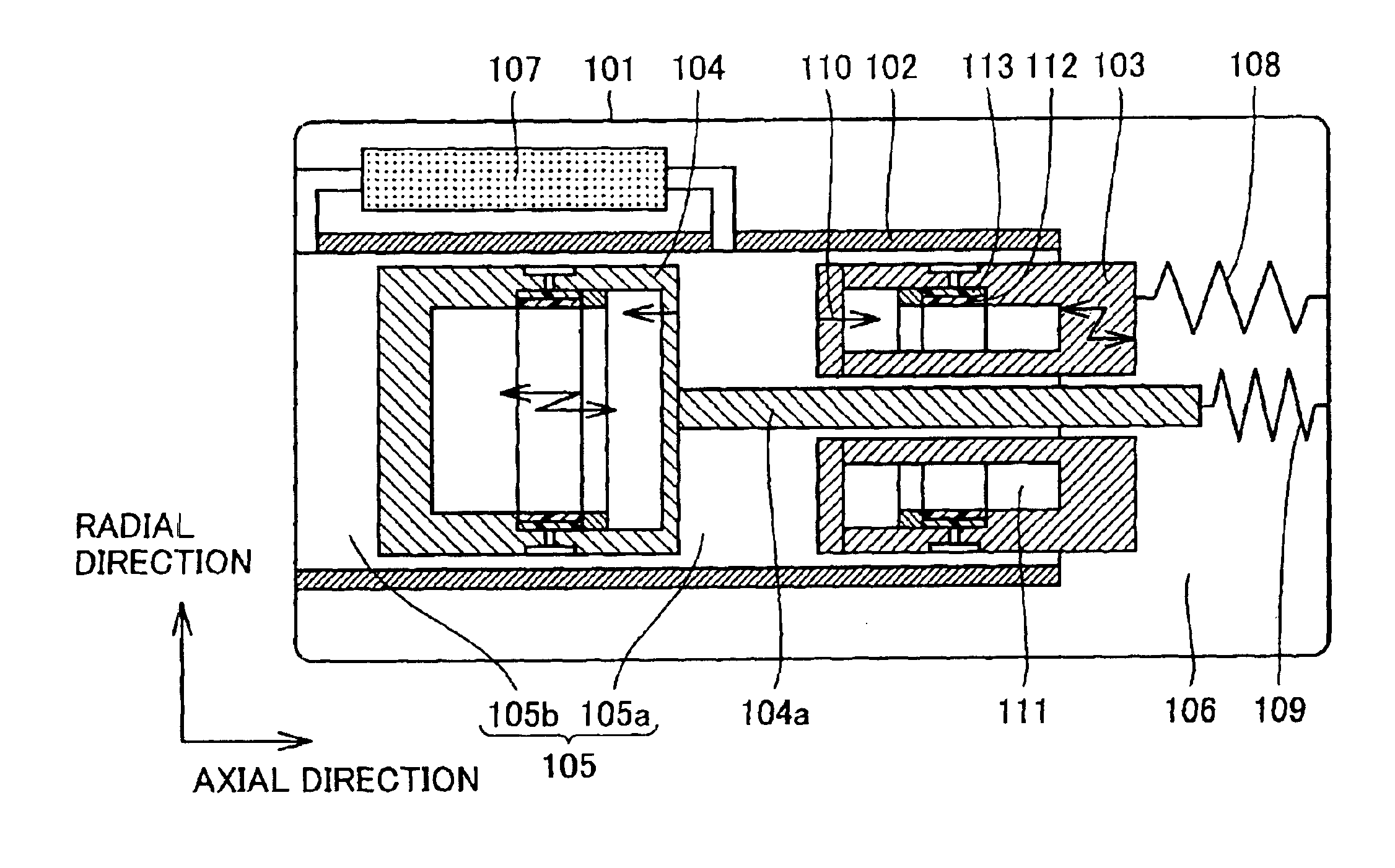
[0139]The structure of a Stirling engine according to this embodiment is schematically described with reference to FIG. 1. In this embodiment, a pressure vessel 101 is filled up with high-pressure helium gas (hereinafter simply referred to as “gas”) as a medium. A piston 103 and a displacer 104 serving as effectors are arranged in a single cylinder 102, so that the piston 103 and the displacer 104 reciprocate respectively.

[0140]The piston 103 divides a space formed by the pressure vessel 102 and the cylinder 102 into two spaces. The first space is a working space 105 defined on a side of the piston 103 closer to the displacer 104. The second space is a back space 106 defined on a side of the piston 103 opposite to the displacer 104.

[0141]The displacer 104 further divides the workin...

second embodiment

[0166](Second Embodiment)

[0167]A Stirling engine according to a second embodiment based on the present invention is now described with reference to the drawings. As to structures identical to those in the first embodiment, detailed description is omitted. The feature of the Stirling engine according to this embodiment resides in the structure of a gas effusion part provided on a piston, and hence only the structure of this gas effusion part is mentioned here.

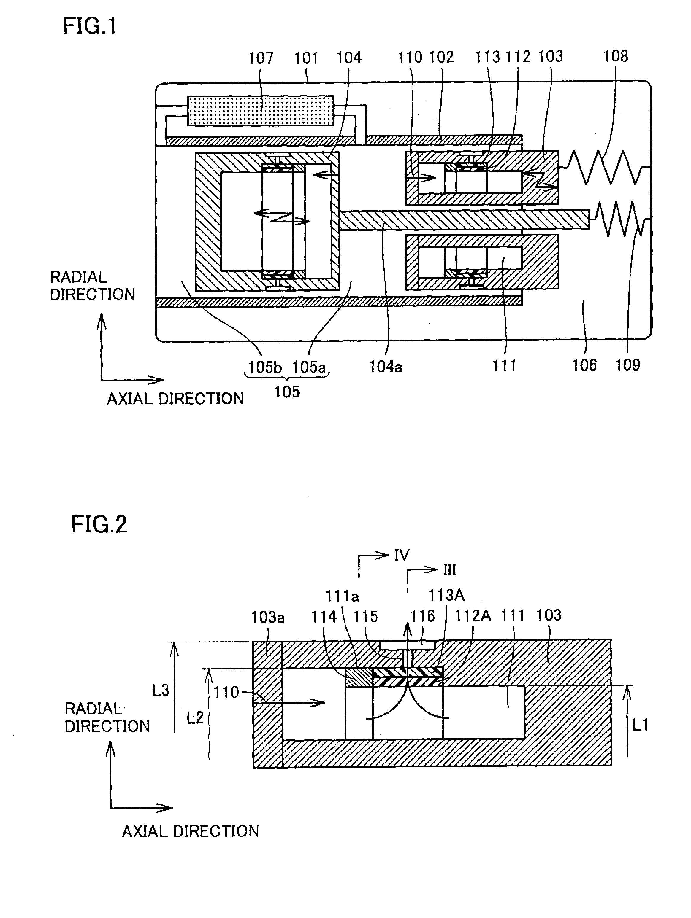
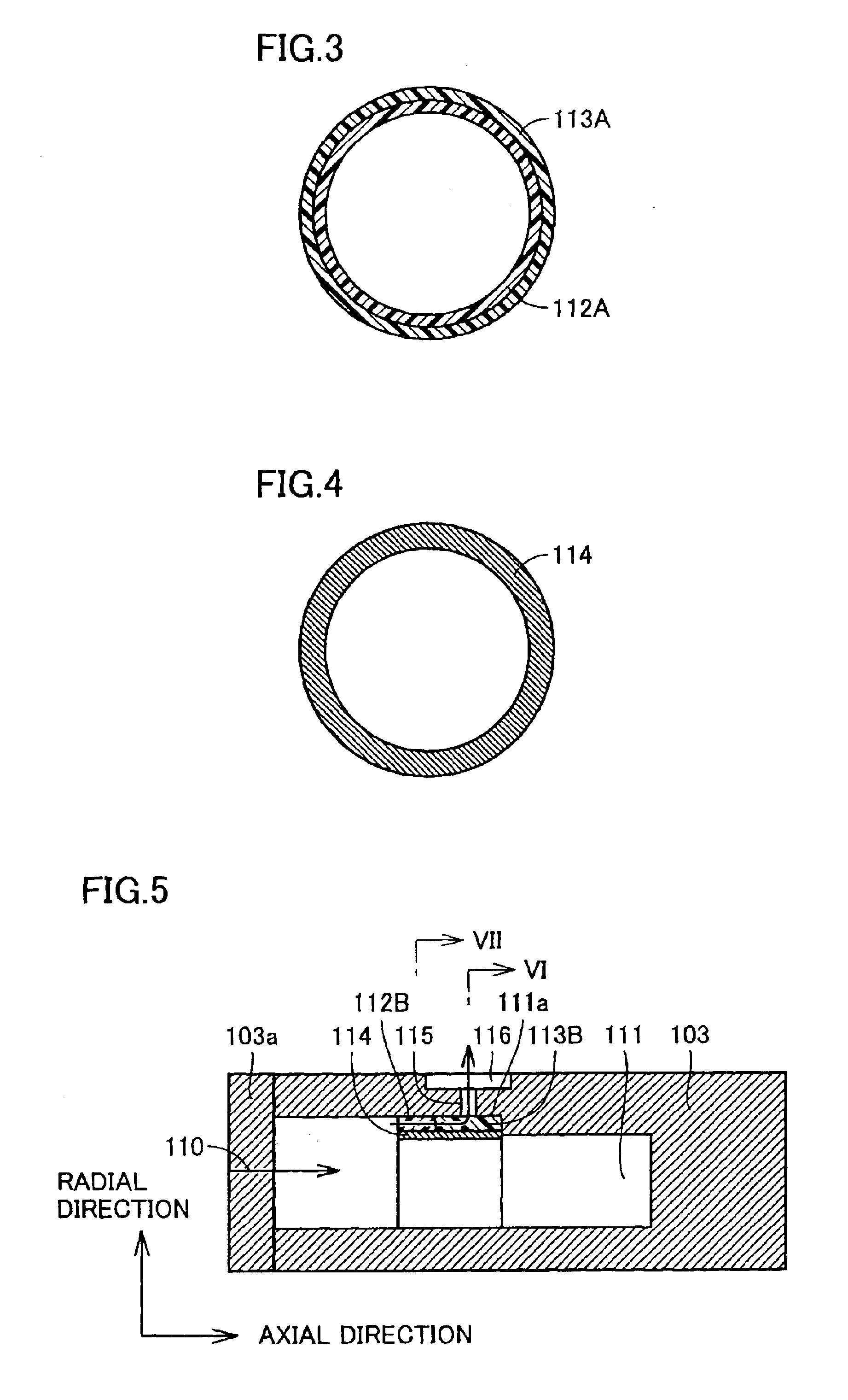
[0168]The structure of the gas effusion part in this embodiment is described with reference to FIGS. 5 to 7. FIG. 5 is a diagram showing the sectional form of a piston 103, FIG. 6 is a sectional view taken along the line VI in FIG. 5, and FIG. 7 is a sectional view taken along the line VII in FIG. 5.

[0169]Referring to FIG. 5, a first porous body 112B having large porosity and a second porous body 113B having small porosity are continuously arranged along the axial direction of a cylinder 102 to be arranged upstream a gas flow di...

third embodiment

[0178](Third Embodiment)

[0179]A Stirling engine according to a third embodiment based on the present invention is now described with reference to the drawings. As to structures identical to those in the first embodiment, detailed description is omitted. The feature of the Stirling engine according to this embodiment resides in the structure of a gas effusion part provided on a piston, and hence only the structure of this gas effusion part is mentioned here.

[0180]The structure of the gas effusion part in this embodiment is described with reference to FIGS. 8 and 9. FIG. 8 is a diagram showing the sectional form of a piston 103, and FIG. 9 is a sectional view taken along the line IX in FIG. 8.

[0181]Referring to FIG. 8, a vent hole 115 is provided perpendicularly (along the diametral direction of a cylinder 102) toward a pressurization chamber 111 in the piston 103, while a first porous body 112C is arranged upstream a gas flow direction and a second porous body 113C is inserted to be ...


PUM


Abstract

A Stirling engine comprises a first porous body having a large hole diameter, a second porous body having a small hole diameter and a ring for fixing the first porous body and the second porous body in a pressurization chamber inside a gas outlet closer to the pressurization chamber.

Description

[0001]This application is the National Phase under 35 U.S.C. §371 of PCT International Application No. PCT / JP01 / 10762, which has an international filing date of Dec. 7, 2001, which designated the United States of America.TECHNICAL FIELD[0002]The first invention relates to a Stirling engine, and more specifically, it relates to the structure of a Stirling engine capable of reliably effusing gas during operation with no clogging in a gas effusion part in a gas effusion structure of a gas bearing applied to each sliding part of the Stirling engine.[0003]The second invention relates to a Stirling engine formed by arranging an effector in a cylinder filled up with high-pressure gas for abruptly expanding the high-pressure gas by reciprocation of the effector thereby absorbing external heat and reducing the external temperature.[0004]The third invention relates to a Stirling engine, and more specifically, it relates to a free-piston Stirling engine.BACKGROUND ART[0005](First Prior Art)[00...

Claims


Application Information

Patent Timeline
Patent Type & Authority Patents(United States)
IPC IPC(8): F02G1/00F02G1/053F02G1/043F25B9/14
CPCF02G1/0435F02G1/053F25B9/14F25B2309/001
Inventor OKANO, SATOSHITANAKA, SHOHZOHUEDA, KAZUHIKOKITAMURA, YOSHIYUKI
Owner SHARP KK
Why Eureka
Try Eureka