Welding shielding gas saver device

a shielding gas and shielding technology, applied in the direction of shielding gas supply/evacuation devices, manufacturing tools, soldering apparatus, etc., can solve the problems of affecting the quality of the weld, wasting shielding gas, small for each occurrence, and affecting the weld. , to achieve the effect of reducing the risk of slipping and slipping, and reducing the welding quality

Inactive Publication Date: 2003-08-26
UTTRACHI GERALD DANIEL
View PDF6 Cites 11 Cited by
  • Summary
  • Abstract
  • Description
  • Claims
  • Application Information

AI Technical Summary

Benefits of technology

It is the principle object of the present invention to provide a means of delivering shielding gas to a MIG welding machine from a shielding gas source such as a high pressure cylinder or gas pipeline which minimizes the storage of shielding gas when the system is stopped and avoids wasted shielding gas each time the system is energized. This system can be used on most industrial MIG welders to obtain significant savings in shielding gas usage. It can be readily added to an existing installation as well as incorporated into new products. The system is designed to be simple, rugged, reliable and require little or no maintenance in an industrial environment. Since a significant amount of shielding gas is saved, fewer cylinders require changing in a given work period where high-pressure cylinders are employed. The wasted time required to change cylinders is reduced and productivity of the welder increased. In addition to the gas savings, the gas flow surge at the start of welding is significantly reduced. This reduces the possibility of air aspiration in the shielding gas stream and resulting poor weld starts. Some additional shielding gas is still provided at the weld start to purge any air that will have backed into the end of the gas hose in the welding torch.

Problems solved by technology

Gas flows much in excess of this level can cause turbulence in the shielding gas stream as it exits the welding torch.
Weld start quality can be impaired because of excess shielding gas flow creating air aspiration into the shielding gas stream.
The wasted shielding gas, although small for each occurrence, can be very significant over time.
(a) One device designed to reduce shielding gas loss is described in U.S. Pat. No. 4,341,237. This device is of complex construction involving several mechanical elements to store and control this excess shielding gas. When properly functioning, this device does accomplish the objective of reducing shielding gas waste. However, it has a number of interconnected parts and must be inspected periodically to assure gas does not leak from the numerous internal connections creating gas waste.
(b) Another method occasionally used to reduce gas surge upon the initiation of the welding arc is to incorporate a flow control orifice at the solenoid end of the shielding gas delivery hose. This device is sometimes sold with the intent to reduce gas waste. The device can give the perception that gas waste is eliminated since the momentary high gas flow surge at the start of welding is reduced, however the gas waste may still occur. Another possible way to incorporate such an orifice restriction is defined in U.S. Pat. No. 4,915,135. The orifice size is selected to restrict gas flow. Depending on the delivery pressure of the regulator these devices employ very small orifices, as small as about 0.030 inches. A filter is often employed to avoid these small orifices becoming clogged by metal flakes or dirt in the gas stream emanating from the cylinder or pipeline. However these devices are usually set to control the gas flow rate well above that desired. This is necessary since differing welding torches, torch lengths and internal plumbing restrictions require differing pressures at the solenoid to obtain the desired gas flow through the torch. The actual pressure needed at the solenoid is indirectly set at the flow control device usually located at the regulator as mentioned above.
Orifice restriction devices help reduce high flow gas surge at the weld start and the resulting degradation of the weld but often do not eliminate or significantly reduce shielding gas waste.
Therefore, if the weld occurs for more than about 3 seconds in time, a similar amount of excess shielding gas is lost as if the restriction orifice was not present.
This system did not perform in the industrial environment to which it is subjected and was withdrawn from sale.
Standard commercially available small inside diameter hoses do not have the needed outside diameter and wall thickness to provide crush and abrasion resistance needed for a welding environment.
These hoses are approximately 0.18 inch outside diameter and are unacceptable, in an industrial environment.
This reduces the possibility of air aspiration in the shielding gas stream and resulting poor weld starts.

Method used


Image

  • Welding shielding gas saver device
  • Welding shielding gas saver device
  • Welding shielding gas saver device

Examples


embodiment

OPERATION-MAIN EMBODIMENT

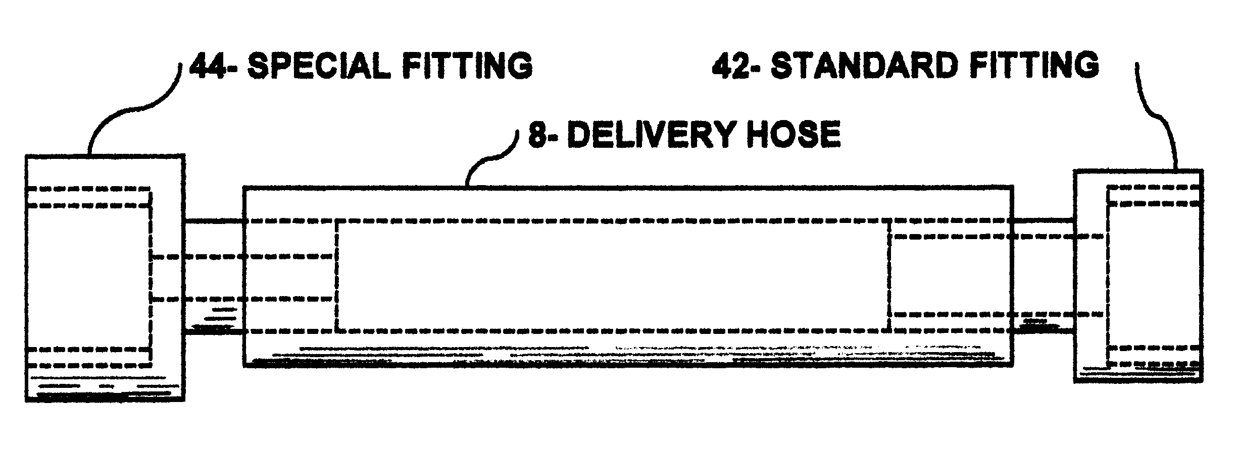
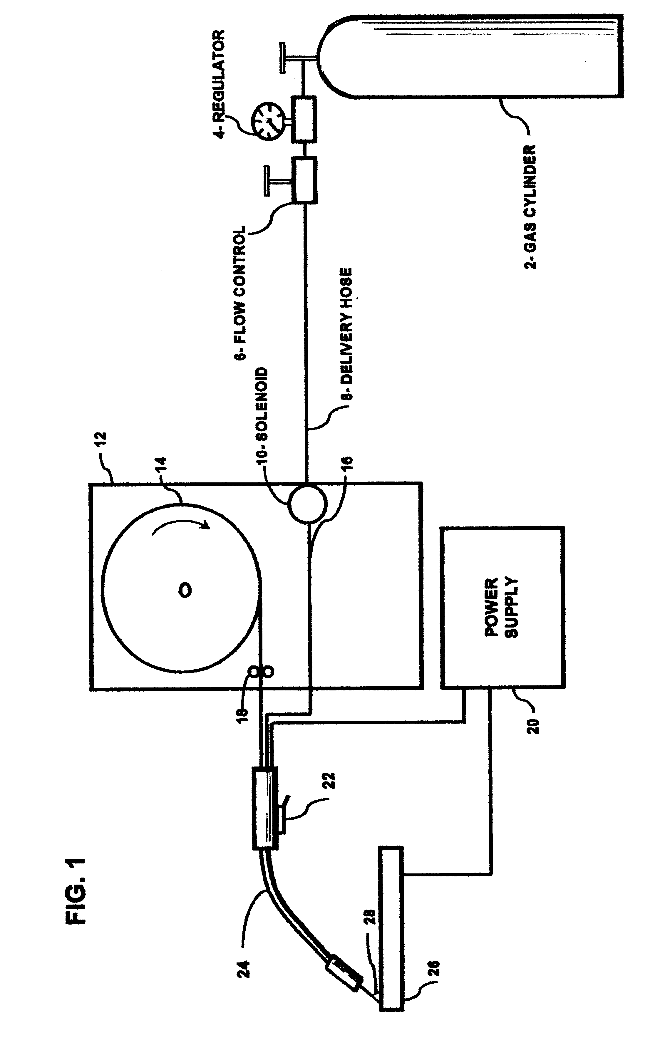
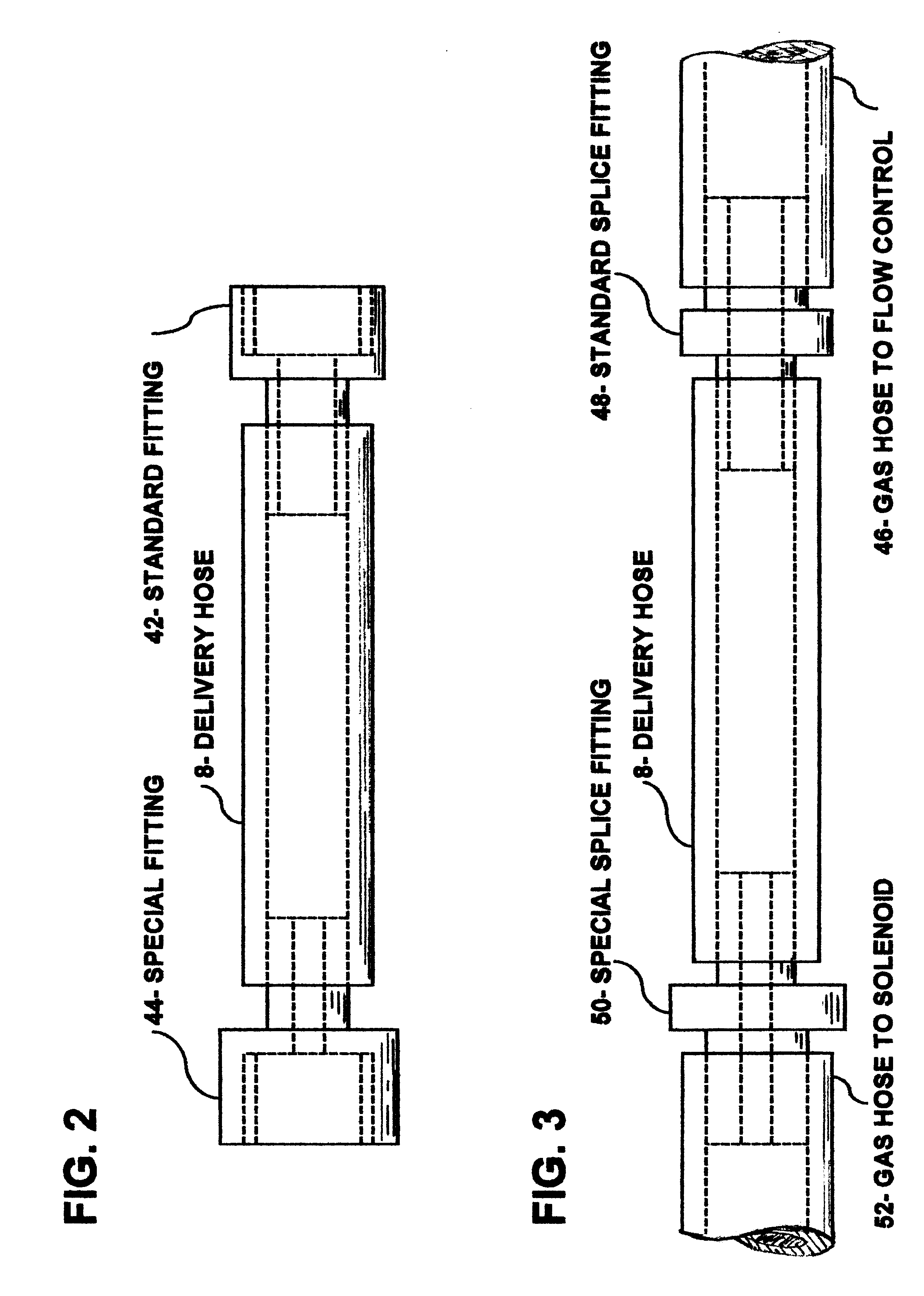
Referring to FIG. 1. When welding is initiated, usually by closing the torch switch 22, the gas solenoid 10 is opened. Shielding gas flows from the cylinder 2, through the regulator 4, to flow control device 6, through the flexible shielding gas delivery hose 8, through the open solenoid 10, through the welding torch 24. The pressure in the shielding gas delivery hose 8 at the solenoid end is established by the restriction created by the flow control device 6 and the pressure drop in the hose and fittings caused by the flow of shielding gas. When welding is stopped, the solenoid 10 is closed; however shielding gas continues to flow into the gas delivery hose 8 until the pressure raises to the fixed output level of the regulator 4, which is commonly 25, 30, 50, or 80 psig. When welding is restarted, the excess gas pressure in the gas delivery hose 8 over that needed to produce the desired shielding gas flow rate is rapidly reduced to that governed by the flow...


PUM

PropertyMeasurementUnit
lengthaaaaaaaaaa
internal diameteraaaaaaaaaa
diameteraaaaaaaaaa

Abstract

This device significantly reduces major reasons for shielding gas waste primarily in metal inert gas welding. Excess shielding gas stored at the end of each weld in the shielding gas delivery hose connecting the gas source to the welding machine creates a shielding gas flow-surge at the next weld start. This gas flow-surge creates shielding gas waste and can cause poor weld start performance. Other methods employed over the years to reduce shielding gas waste have been either complex, leaked, were not sufficiently robust for the environment, provided only partial solutions or did not provide shielding gas savings for welds longer than about 3 seconds. This device includes a delivery hose connecting the shielding gas supply to the welding machine, which has a small internal volume and a gas surge-restricting orifice at the gas solenoid end of the hose.

Description

1. Field of InventionThis invention relates to savingS of 50% or more of shielding gas primarily in the MIG welding process while improving weld start quality.2. Description of Prior ArtGas metal arc welding (GMAW) is commonly referred to as metal inert gas welding (MIG). The term MIG welding is used for the purposes of this invention. In the MIG welding process molten metal is produced by an electric arc. This molten metal is derived from the materials to be welded and a filler wire. The filler wire is fed into the arc zone by a feeding mechanism. The molten weld metal is protected from the surrounding air by a shielding gas. A suitable power source is connected between the workpiece to be welded and to the filler wire passing though a welding torch. Welding power, welding filler wire and shielding gas are usually transported through the torch. The welding torch is usually attached to a flexible cable assembly and is manipulated by the welding operator.The shielding gas employed to...

Claims


Application Information

Patent Timeline
Patent Type & Authority Patents(United States)
IPC IPC(8): B23K9/32
CPCB23K9/325
Inventor UTTRACHI, GERALD DANIEL
Owner UTTRACHI GERALD DANIEL
Why Eureka
Try Eureka