Manual round hay bale wrapper

a hay bale and wrapper technology, applied in the field of manual round hay bale wrappers, can solve the problems of increased input costs and continued hay production costs, and achieve the effects of improving production efficiency, improving input costs, and improving preservation

Inactive Publication Date: 2013-06-04
BAUER GARY PAUL
View PDF20 Cites 1 Cited by
  • Summary
  • Abstract
  • Description
  • Claims
  • Application Information

AI Technical Summary

Benefits of technology

[0002]The machine consists of a base on which all other components rest. The base is a ladder frame sufficient to carry the weight of the entire apparatus and it rests upon the ground or other level surface. The frame has affixed to its upper surface, four wheels mounted and aligned in the direction of the frame so that a trolley which rests above it is supported by those four wheels which are captured within a “U” channel. The “U” channel is the bottom part of the frame for the dolly. At each end of the “U” channel, stops are welded limiting travel so that the trolley does not run beyond the “U” channel. Those wheels and the channel allow the trolley to move laterally to accommodate bales of varying widths. The trolley is also built as a ladder frame which rests atop the base with “U” channel as described above. Cross members are attached and four pillow blocks are mounted in alignment with the cross members. The pillow blocks support a shaft which is free to rotate and connects one pillow block to the pillow block on the opposite cross member so that there are two complete axle assemblies atop the cross members and each axle supports the ring above allowing it to rotate. To the interior of the pillow block and immediately adjacent to it is a flat disk which is used to capture and retain the ring which rides atop the two axles. To the interior of each disk is a wheel designed to provide a smooth cushioned and low resistance surface for the large ring above to turn. The third and final component is the large ring of sufficient size to accommodate bales of any diameter. The rings are constructed in such a manner as to be easily disassembled to minimize storage and allow it to be easily transported when broken down. There are two large rings joined at the points where the ring is easily disassembled with cross members giving the rings a parallel and rigid conformation. The cross members are tubular and have spring clips locking the sections onto the cross brace. The cross brace could also be secured with bolts or the entire ring could be welded and function in the same fashion. Once the rings have been assembled with the cross braces, the entire unit can then be placed atop the axles and prepared for the wrapping material. The wrapping material is attached to the inside of the large rings with one roll at opposite locations. The brackets welded to the interior of the ring contain holes which align with nylon fittings designed to seat within the inner core of the wrapping material roll and allow the operator to select the tension appropriate for the material being wrapped by tightening a fitting which increases rolling tension as the fitting is advanced.

Problems solved by technology

The cost of production of hay continues to rise with increased input costs making it more important than ever to preserve as much of the hay and the quality of the hay whenever possible.

Method used


Image

  • Manual round hay bale wrapper
  • Manual round hay bale wrapper
  • Manual round hay bale wrapper

Examples


Embodiment Construction

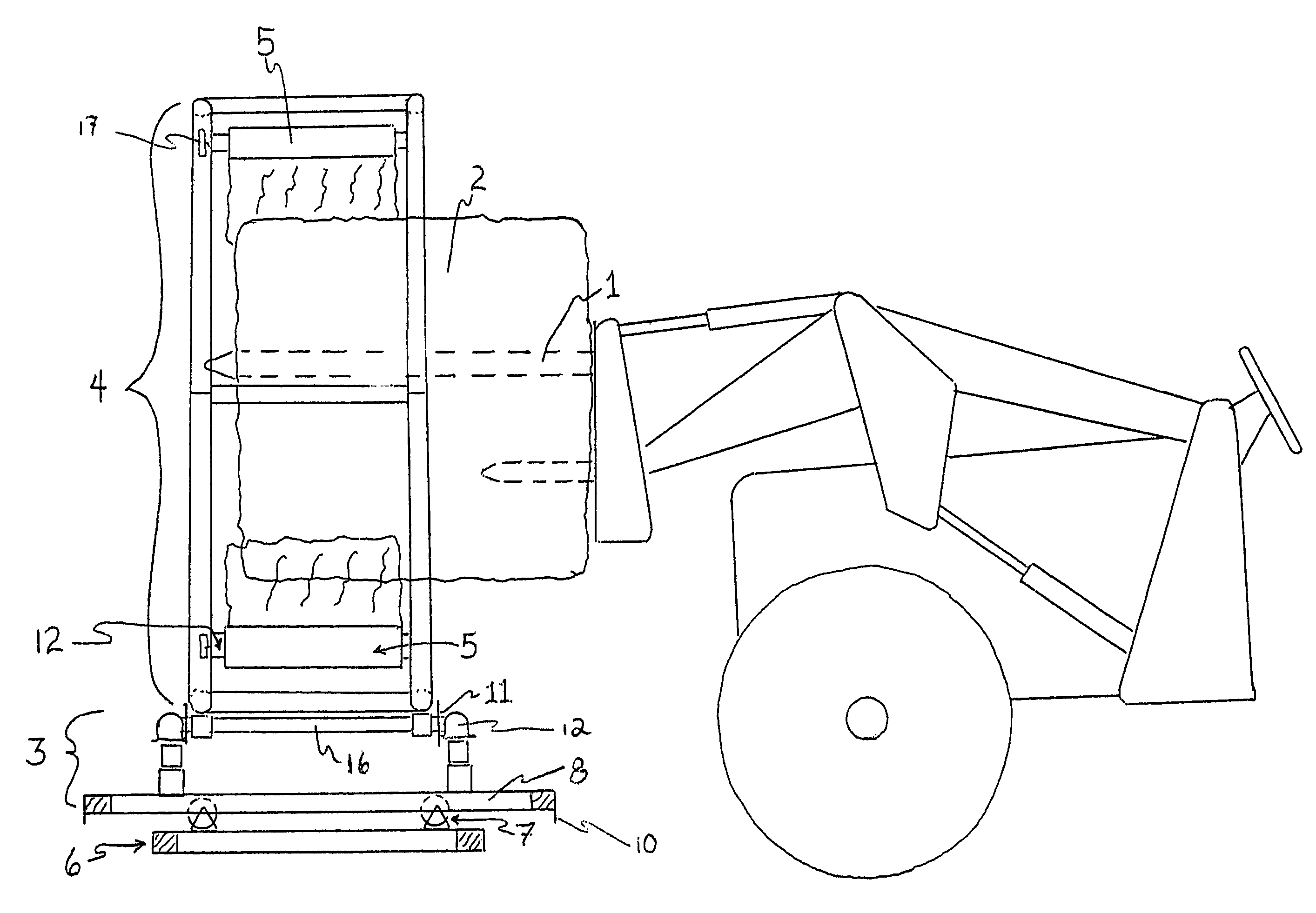
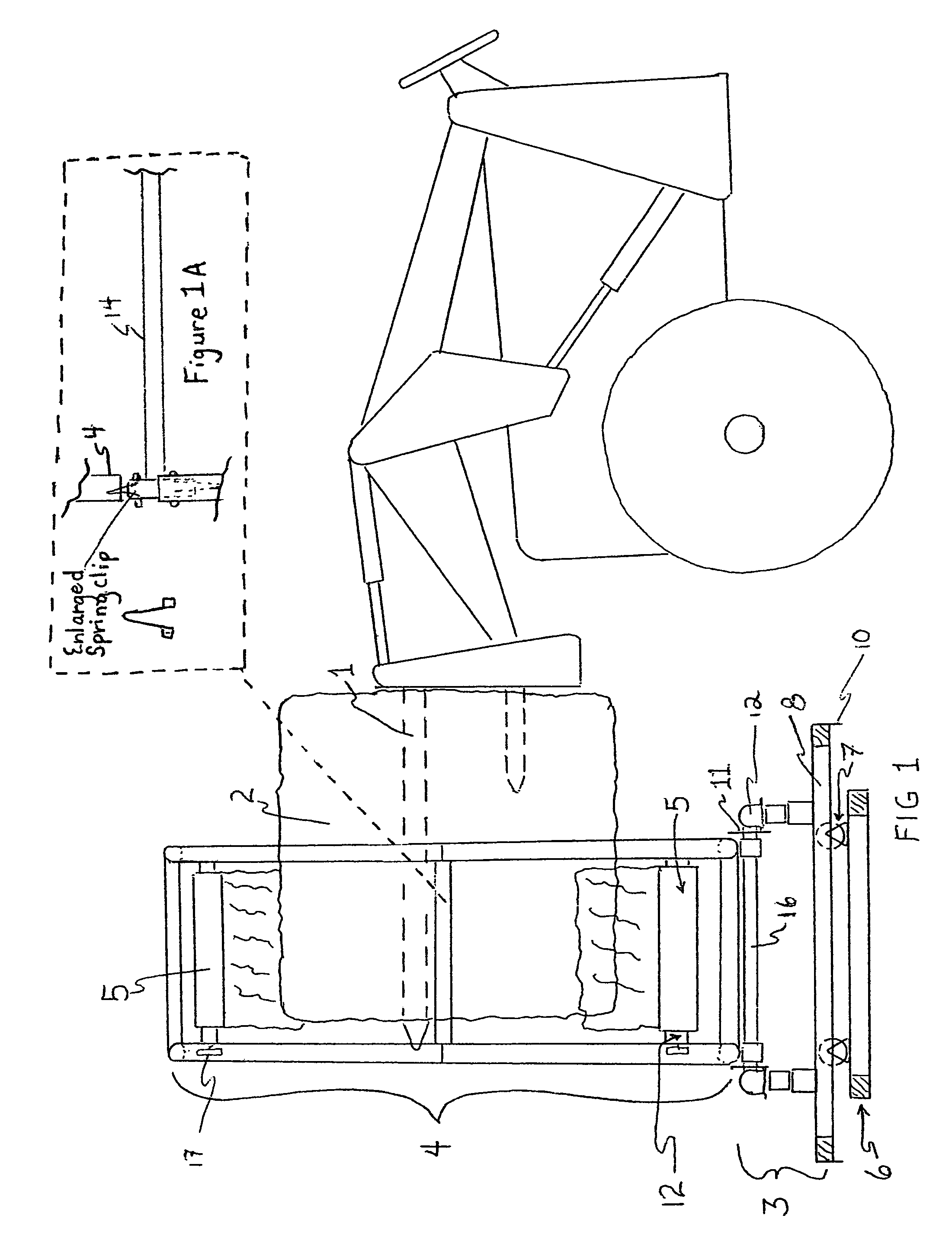
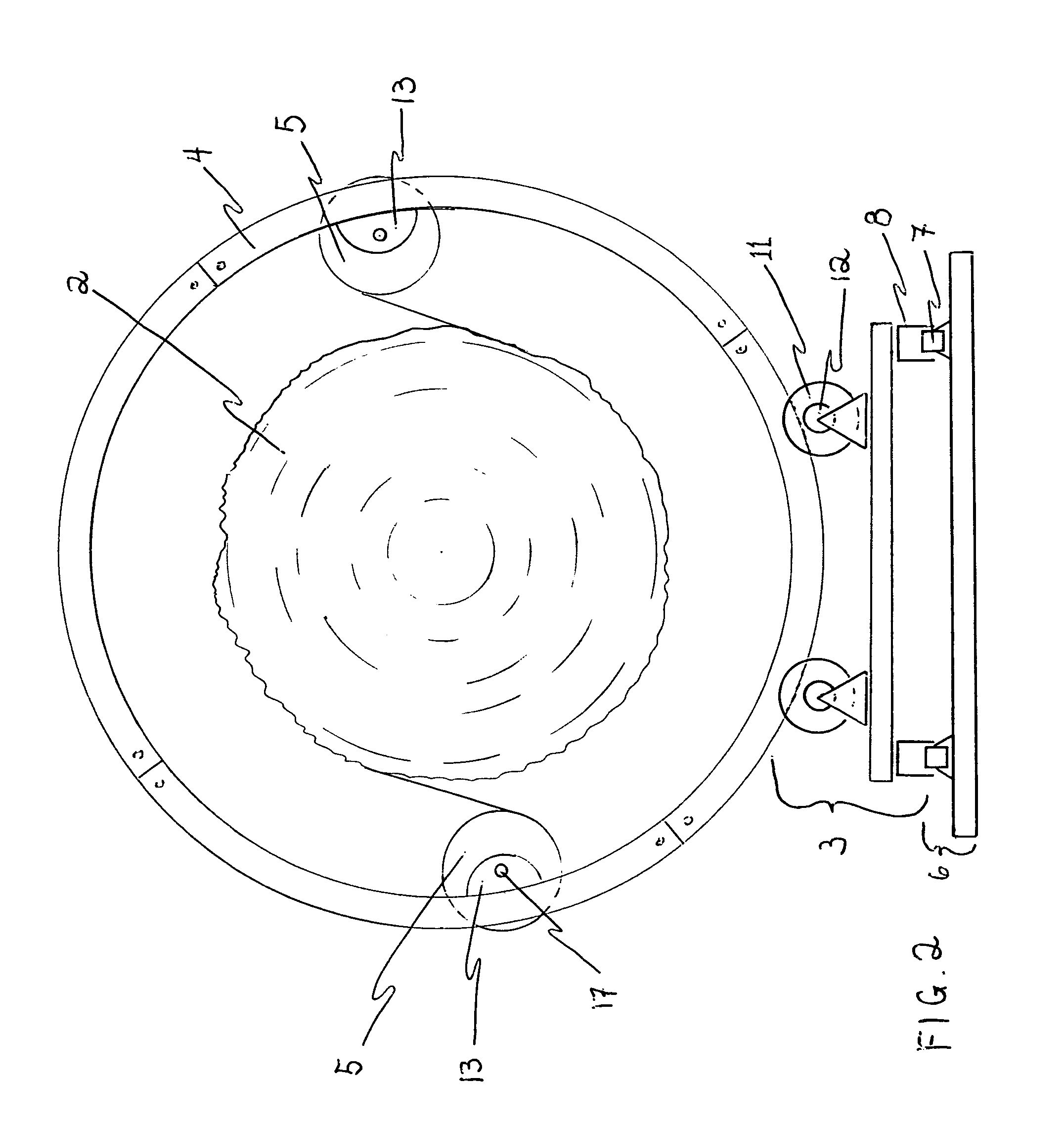
[0012]FIG. 1 Shows the machine from the side and a tractor with a spear (1) attached to a tractor front-end loader and a bale (2) suspended by that spear. The tractor is stationary and the bale is suspended over the trolley unit (3) and centered within the ring (4) which is free to rotate about the bale (in that picture the wrap (5) is tucked into the twine encircling the bale and started in a counterclockwise manner, but also could be rotated clockwise). The supporting base (6) has four wheels (7) mounted on the top of the base and captured in the lower “U” channels (8) [also depicted in FIG. 2] which comprise the lower frame unit of the trolley unit allowing the trolley to travel freely across the width of the bale until the trolley reaches the stops (10) attached to the end of the “U” channels (8). In this manner the entire ring can be moved toward or away from the tractor to allow coverage of the entire width of the bale. The ring is segmented with four segments (14) on each sid...


PUM

PropertyMeasurementUnit
diameteraaaaaaaaaa
diameteraaaaaaaaaa
diameteraaaaaaaaaa

Abstract

This is a machine to allow a single individual to manually wrap round hay bales with any type of film or net wrap. It allows the operator to position a round bale suspended on a bale spear and centered within the bale wrap ring to turn the ring which contains the wrap material clockwise or counterclockwise about the bale as the wrap covers the bale about its circumference. The ring can also be moved left and right to ensure full coverage of the bale in spite of widths and the ring is large enough to accommodate bales of any diameter up to six foot and can be easily adapted to bales of even larger diameter if round balers are produced in excess of six foot in diameter.

Description

[0001]The inventor hereby claims the benefits associated with the Provisional Patent applied for on 28 May 2009, Application No. 61 / 181,908, Name of Inventor—Gary Paul BauerDESCRIPTION OF THE MANUAL BALE WRAP MACHINE[0002]The machine consists of a base on which all other components rest. The base is a ladder frame sufficient to carry the weight of the entire apparatus and it rests upon the ground or other level surface. The frame has affixed to its upper surface, four wheels mounted and aligned in the direction of the frame so that a trolley which rests above it is supported by those four wheels which are captured within a “U” channel. The “U” channel is the bottom part of the frame for the dolly. At each end of the “U” channel, stops are welded limiting travel so that the trolley does not run beyond the “U” channel. Those wheels and the channel allow the trolley to move laterally to accommodate bales of varying widths. The trolley is also built as a ladder frame which rests atop th...

Claims


Application Information

Patent Timeline
Patent Type & Authority Patents(United States)
IPC IPC(8): B65B11/02
CPCA01F15/071A01F2015/0725
Inventor BAUER, GARY PAUL
Owner BAUER GARY PAUL
Why Eureka
Try Eureka