Eureka AIR delivers breakthrough ideas for toughest innovation challenges, trusted by R&D personnel around the world.

Push-pull water diversion valve for engineering geologic drilling water pressing test

A technology of water pressure test and engineering geology, applied in valve details, control valve, valve device, etc., can solve the problem of inability to carry out double-plug continuous water pressure, unable to complete large flow water pressure test, unable to complete drilling water pressure tasks, etc. question

Pending Publication Date: 2018-01-09
CHINA WATER RESOURCES BEIFANG INVESTIGATION DESIGN & RES
View PDF9 Cites 4 Cited by
  • Summary
  • Abstract
  • Description
  • Claims
  • Application Information

AI Technical Summary

Problems solved by technology

The single-pipe top-pressure expansion plug pressurizes water is the traditional method. It is a single-plug pressurized water, and the water is pressed one after another when drilling. Pneumatic pipes are easy to accumulate in the borehole, difficult to pull out, and cannot complete the task of drilling and pressing water in deep holes of more than 200 meters; most of the hydraulic plugs in use now use two sets of water supply pipelines (one set of expansion plugs, one set of pressure plugs). water passage), there is also a small flow water diversion valve with integrated functions, but it cannot complete the high flow pressure water test

Method used


Image

  • Push-pull water diversion valve for engineering geologic drilling water pressing test

Examples


Embodiment Construction

[0012] The present invention will be described in further detail below in conjunction with the accompanying drawings and specific embodiments.

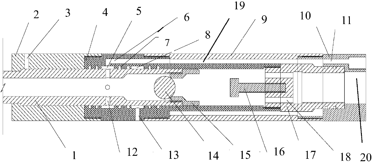
[0013] Such as figure 1 Shown, the present invention is used for the push-pull type diverter valve of engineering geology borehole pressurized water test, comprises upper valve body 2, lower valve body 4, ball valve seat 15, outer pipe 9, end cover 10, upper valve body 2 lower ends and The upper end of the lower valve body 4 is connected by a screw thread, and the outer wall of the lower valve body 4 is a stepped structure with a thick upper part and a thinner lower part. In the tube 9, an annular cavity 19 is formed, and the lower end of the outer tube 9 is connected to the end cover 10 with the inner through hole 20 and the bypass hole 11 to form a valve chamber; the push-pull core rod 1 is located in the valve chamber, and the lower end is connected to the ball valve seat through a screw. 15. The steel ball 14 is placed between th...


PUM


Abstract

The invention discloses a push-pull water diversion valve for an engineering geologic drilling water pressing test. The push-pull water diversion valve comprises a push-pull core rod, an upper valve body, a lower valve body, a supporting seat, a ball valve seat, a moving steel ball and a steel ball ejector rod, the upper valve body, the lower valve body and the supporting seat are connected through threads to form a valve chamber, an outer pipe is connected with an end cap and the valve chamber through threads, the supporting seat and the lower valve body as well as the steel ball ejector rodform a whole inside the outer pipe through threads, the core rod and the ball valve seat are connected in the valve chamber composed of the upper and lower valve bodies through threads, and the movingsteel ball is arranged on the upper portion of the ball valve seat. A ventilation hole is drilled in the outer side of the upper valve body, two water feeding ring grooves 2 and two water feeding holes are formed in the inner wall of the lower valve, and water feeding holes in the core rod and water feeding holes of the end cap can be communicated with the water feeding holes of the lower valve body, water feeding holes of the supporting seat and an inner cavity passage of the lower valve body. The push-pull water diversion valve is simple in structure, switching and closing of water passagescan be realized by moving the core rod in the valve chamber to different positions, and working requirements on expanding plug water pressing, water pressing test, drill rod water pressure release and capsule pressure release of the drilling water pressing test can be met.

Description

technical field [0001] The invention relates to a water diversion valve, in particular to a push-pull water diversion valve used for engineering geological borehole pressure water test. Background technique [0002] There are three types of expansion plugs in the current borehole pressure water test: single-pipe top pressure type, pneumatic type and hydraulic type. The single-pipe top-pressure expansion plug pressurizes water is the traditional method. It is a single-plug water pressurization, and the water is pressed one after another after drilling. It is impossible to carry out double-plug continuous pressurization, which is inefficient; Pneumatic pipes are easy to accumulate in the borehole, difficult to pull out, and cannot complete the task of drilling and pressing water in deep holes over 200 meters; most of the hydraulic plugs currently in use use two sets of water supply pipelines (one set of expansion plugs, one set of pressure plugs). water passage), also has a s...

Claims


Application Information

Patent Timeline
IPC IPC(8): E21B47/00F16K27/12F16K27/02F16K15/04
Inventor 陈中和高义军赵秋甘杰郭智民林大明李军军张英杰丁东亮王云
Owner CHINA WATER RESOURCES BEIFANG INVESTIGATION DESIGN & RES
Why Eureka
Eureka Blog
Learn More