Functionality test method

a functionality and test method technology, applied in the direction of power supply testing, testing/monitoring control systems, instruments, etc., can solve the problems of reducing the efficiency of the power generation system, affecting the normal operation of the technical system, and the technical system being unavailabl

Inactive Publication Date: 2007-06-26
GENERAL ELECTRIC CO
View PDF7 Cites 9 Cited by
  • Summary
  • Abstract
  • Description
  • Claims
  • Application Information

AI Technical Summary

Problems solved by technology

However, due to the nature of the functionality test the normal operation of the technical system has to be interrupted.
Accordingly, the technical system is not available during the duration of the test procedure of the technical component.
For example, power generation systems that have to be shut-down for a component test will not produce power during the test procedure, thus reducing the efficiency of the power generation system.
Furthermore, the technical systems are often complex in that they include a plurality of different technical components.
This, however, reduces the average time of normal operation of the technical system between two successive tests.
Typically, wind turbines are located at remote sites and subject to harsh climate.
Furthermore, maintenance costs for remote turbine sites are relatively high so that it is desirable to reduce the frequency of such maintenance procedures.

Method used


Image

  • Functionality test method
  • Functionality test method
  • Functionality test method

Examples


Embodiment Construction

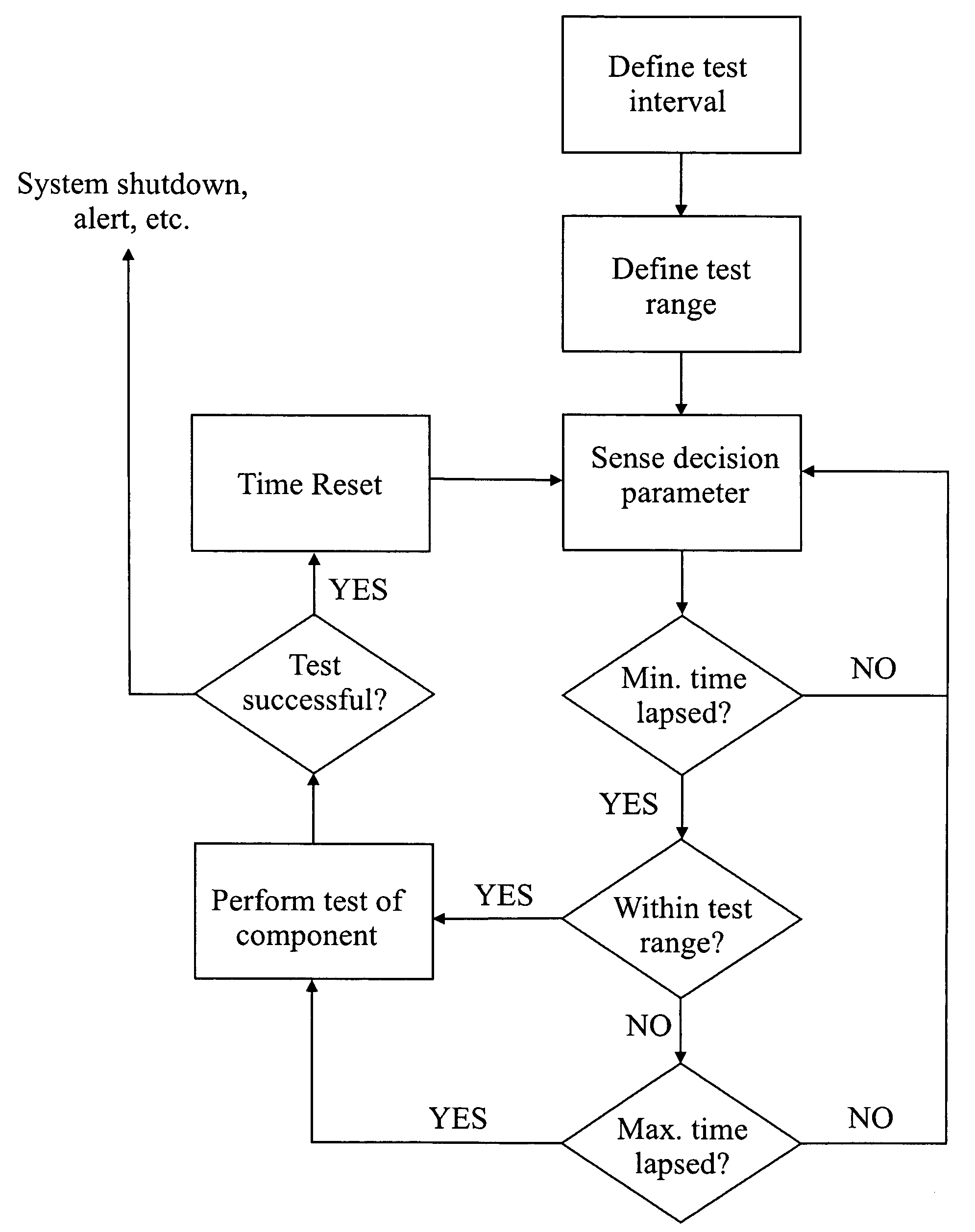
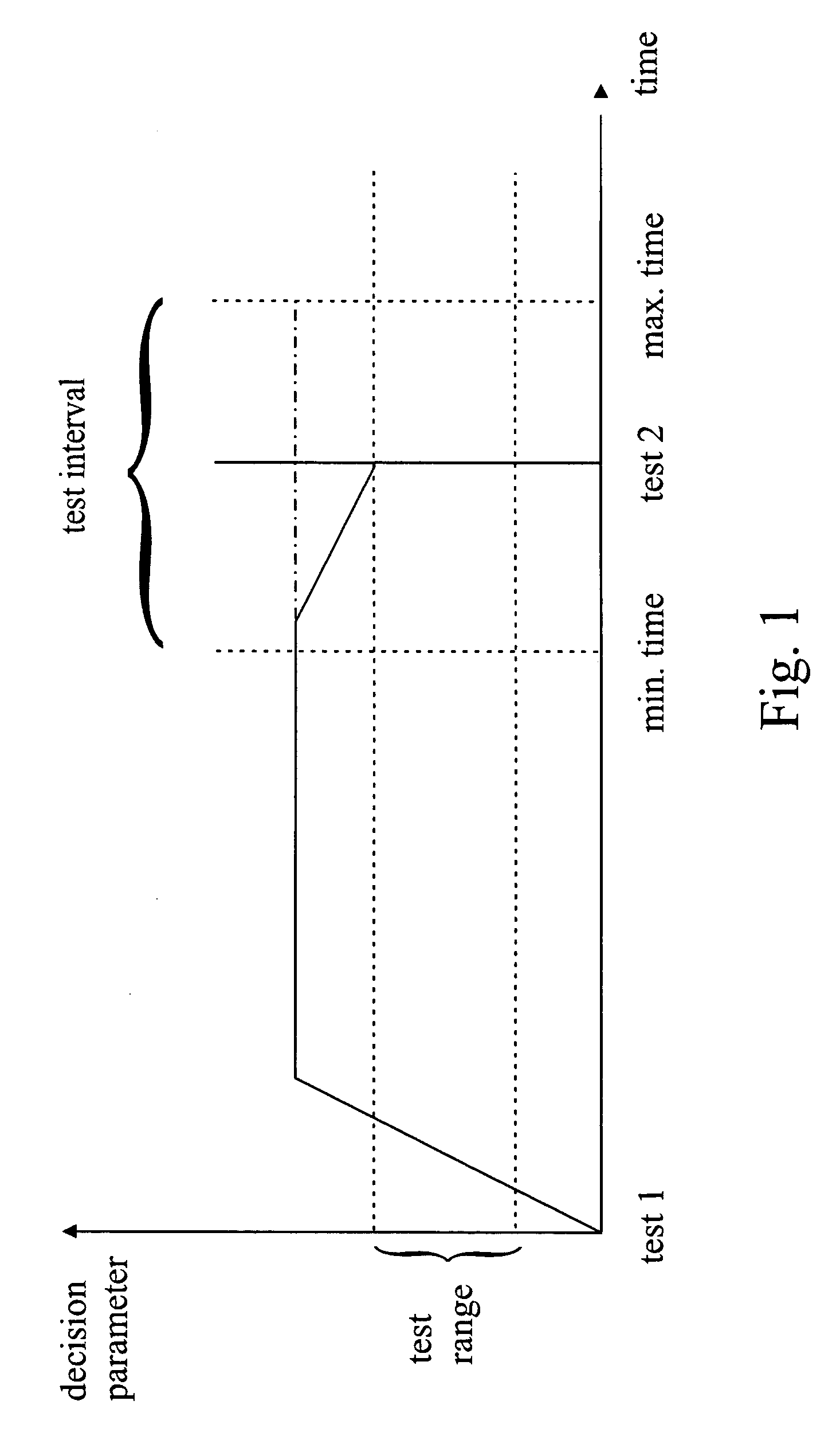
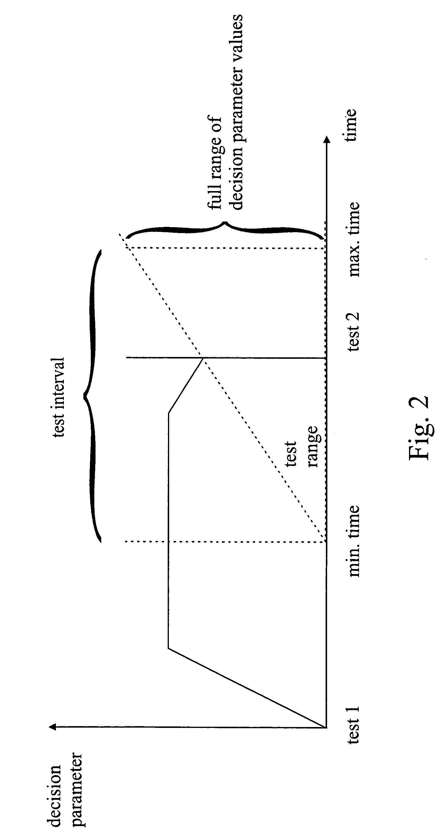
[0013]FIG. 1 is a time scheme of a functionality test procedure according to an embodiment of the present invention. Therein, the value of a decision parameter versus time is shown. As an example, the input power of a wind turbine is selected as the decision parameter. Furthermore, as an example the technical component to be tested is a battery for an emergency pitch drive and the mechanical power input into the generator is selected as a decision parameter. However, it should be understood that the following explanations are not restricted to wind turbines, a battery test or to input power. It should be apparent to one skilled in the art how the following explanations may apply to other technical systems and / or components and / or other decision parameters. Furthermore, FIG. 4 shows a flow chart of the functionality test method and should be referred to when reading the explanations below.

[0014]First, a maximum time interval between two successive tests is defined which corresponds t...


PUM


Abstract

A functionality test method for a technical system having at least one technical component to be regularly tested. The method including the steps of defining a test interval by setting a minimum time interval and a maximum time interval between two successive tests of the technical component, defining a test range for a decision parameter, sensing an actual value of the decision parameter, and performing a functionality test of the technical component if the minimum time interval between two successive tests of the technical component has elapsed and the sensed actual value of the decision parameter is within the predefined test range, or the maximum time interval between two successive tests of the technical component has elapsed.

Description

BACKGROUND OF THE INVENTION[0001]This invention relates generally to a method for performing a functionality test of a technical component in a technical system.[0002]Technical systems often include a plurality of individual technical components. To obtain troublefree operation of the technical system or to detect failures or wear of the components, functionality tests of the components are performed in regular intervals. These functionality tests are especially important for components which are relevant for the operational safety of the technical system, e.g. emergency shut-down systems. Also, there exist legal directives prescribing functionality tests at certain intervals.[0003]However, due to the nature of the functionality test the normal operation of the technical system has to be interrupted. Accordingly, the technical system is not available during the duration of the test procedure of the technical component. For example, power generation systems that have to be shut-down ...

Claims


Application Information

Patent Timeline
Patent Type & Authority Patents(United States)
IPC IPC(8): G01R31/26G01M99/00
CPCG05B23/0283
Inventor MIDDENDORF, JOERGHAGEDORN, RALF
Owner GENERAL ELECTRIC CO
Why Eureka
Try Eureka