Earthing electric wire and water-stopping method therefor

a technology of earthing electric wire and water stopping method, which is applied in the direction of coupling device connection, insulation conductor/cable, cables, etc., can solve the problems of water stopping structure affecting, and achieve the effect of simple operation without increasing the volume of the electric wire terminal portion

Active Publication Date: 2007-07-03
AUTONETWORKS TECH LTD +2
View PDF21 Cites 18 Cited by
  • Summary
  • Abstract
  • Description
  • Claims
  • Application Information

AI Technical Summary

Benefits of technology

[0007]It is an object of the invention to perform the treatment of water-stopping the earthing electric wire reliably by the simple operation without increasing the volume of an electric wire terminal portion so much.
[0009]According to this construction, in addition to the water-stopping agent feeding step of feeding the water-stopping agent to one terminal of the earthing electric wire, the pressure reducing step of reducing the pressure on the inner side of the insulating material by sucking the air from the other terminal of the earthing electric wire is performed so that the water-stopping agent fed can penetrate sufficiently into the inner side of the coating material. As a result, the reliable water-stopping treatment can be realized without changing the volume of the electric wire terminal portion substantially. In the earthing electric wire subjected to the water-stopping treatment by that method, the water passage on the inner side of the insulating material can be reliably blocked to prevent the water from invading into the vehicle-mounted circuit from the earth connection portion along the earthing electric wire.
[0011]Here, at the terminal fixing step, it is preferred that an earthing connection terminal to be connected with the body earth of the vehicle is fixed on one terminal of the earthing electric wire. As a result, the invasion of the water into the earthing electric wire can be blocked on the entrance side (i.e. on the side of the earthing connection terminal).

Problems solved by technology

In this case, the water-stopping structure may be affected by the addition of an external force accompanying the work of fixing that terminal.

Method used


Image

  • Earthing electric wire and water-stopping method therefor
  • Earthing electric wire and water-stopping method therefor
  • Earthing electric wire and water-stopping method therefor

Examples


example

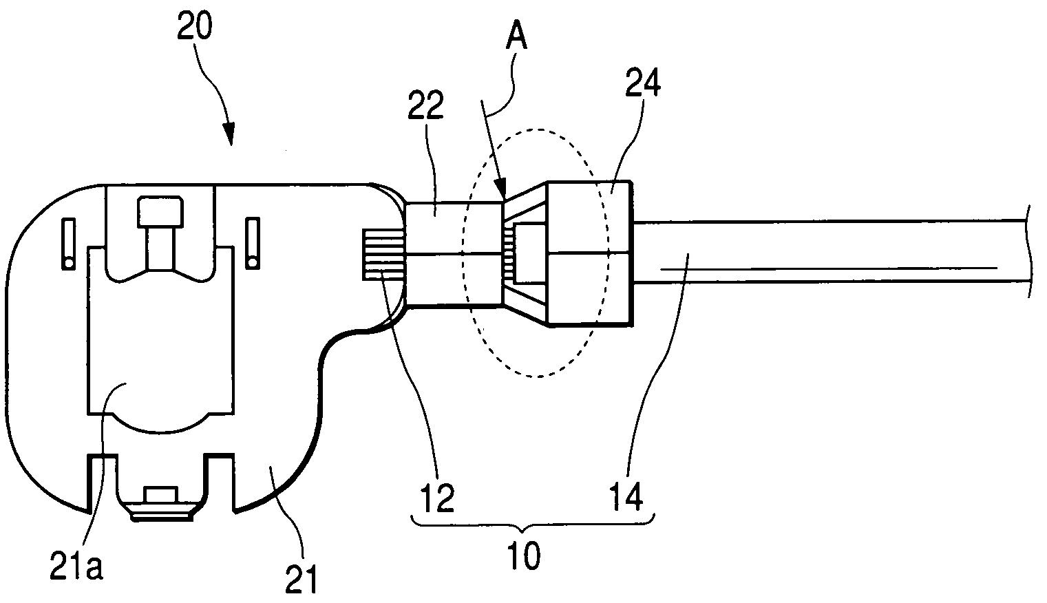
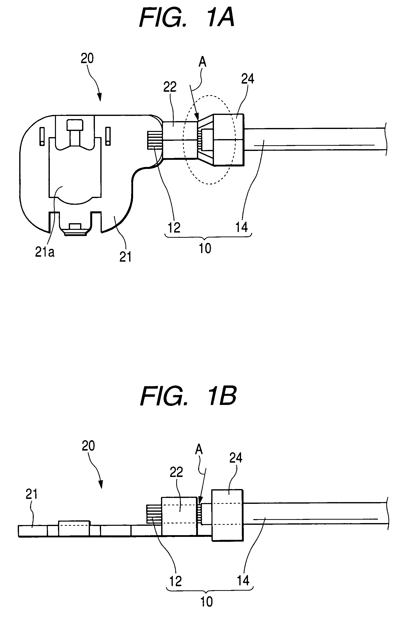
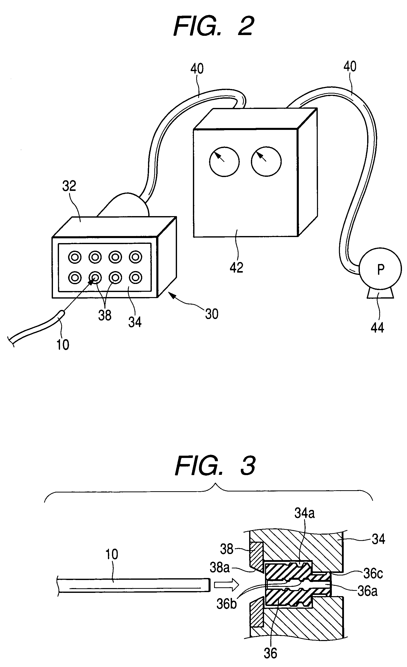
[0041]The water-stopping treatment was performed by the method, as shown in FIGS. 1A and 1B to FIG. 3, under the following conditions:[0042]Length of Electric Wire: 0.5 to 1.5 m;[0043]Sectional Area of Electric Wire: 2 mm2;[0044]Water-Stopping Agent Used: Silicone Rubber[0045](Viscosity: 0.6 Pa·s);[0046]Dripping Quantity of Water-Stopping Agent:[0047](about 1 to 2 droplets);[0048]Pressure at Reduced Time: 80 KPa; and[0049]Pressure Reducing Time: 10 to 20 seconds from Feeding Instant of Water-Stopping Agent.

[0050]As a result of this treatment, it could be confirmed that the water-stopping agent had penetrated into the inner side of the insulating material 14 over the region of 10 to 50 mm from the electric wire terminal. Moreover, this electric wire was subjected to a cold temperature endurance test over 1,000 cycles within a temperature range of −40° C. to 120° C. and a high temperature protracted test at a temperature of 160° C. or lower over 120 hours. It could also be confirmed e...


PUM

PropertyMeasurementUnit
initial viscosityaaaaaaaaaa
temperatureaaaaaaaaaa

Abstract

An earthing electric wire including a conductor; and a coating material outside of the conductor, wherein a water-stopping agent having a flowability is located between the conductor and the coating material on an earthing connection terminal side of the earthing electric wire for connecting a circuit mounted on a vehicle with the earth.

Description

BACKGROUND OF THE INVENTION[0001]1. Field of the Invention[0002]The present invention relates to a technique for water-stopping an earthing electric wire to connect an electric circuit to be mounted on a vehicle or the like with the earth.[0003]2. Description of the Related Art[0004]Generally, the earthing electric wire is so connected with a suitable earthing portion (e.g., the body of a vehicle) that an earthing connection terminal fixed on its terminal is exposed to the outside. Therefore, water may invade from that exposed terminal and may obstruct the normal action of a circuit if it invades into the circuit through the inner side of a coating material.[0005]As a method for water-stopping such earthing electric wire, therefore, a highly viscous seal resin is molded to cover the electric wire terminal, on which the earthing connection terminal is fixed, as disclosed in JP-A-2001-167821 (page 4, FIG. 4).[0006]In the method of molding the resin around the electric wire terminal, a...

Claims


Application Information

Patent Timeline
Patent Type & Authority Patents(United States)
IPC IPC(8): H01R9/05H01B7/282H01R43/00H01B13/32H01R4/66H01R11/12H01R13/52H02G15/02
CPCH01R4/66H01R13/5216H01R11/12Y10T29/49176Y10T29/49174
Inventor TANAKA, TETSUJIHIRAI, HIROKISAKAI, YOSHITOSUZUKI, TOSHIAKI
Owner AUTONETWORKS TECH LTD
Why Eureka
Try Eureka