Composite fiber radial compression members in an umbilical

a technology of radial compression and composite fiber, applied in the field of umbilicals, can solve the problems of umbilicals being subjected to increasingly higher radial compression forces

Active Publication Date: 2007-07-03
OCEANEERING INTERNATIONAL
View PDF13 Cites 16 Cited by
  • Summary
  • Abstract
  • Description
  • Claims
  • Application Information

AI Technical Summary

Problems solved by technology

Due to increased operating / installation depths of umbilical systems, umbilicals are typically subjected to increasingly higher levels of radial compression forces, e.g. by installation equipment during the actual installation process.

Method used


Image

  • Composite fiber radial compression members in an umbilical
  • Composite fiber radial compression members in an umbilical

Examples


Embodiment Construction

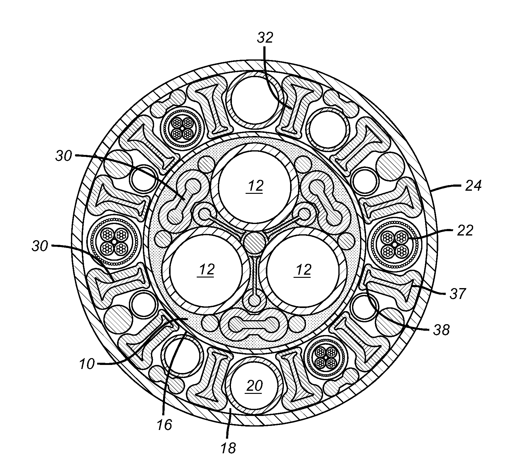
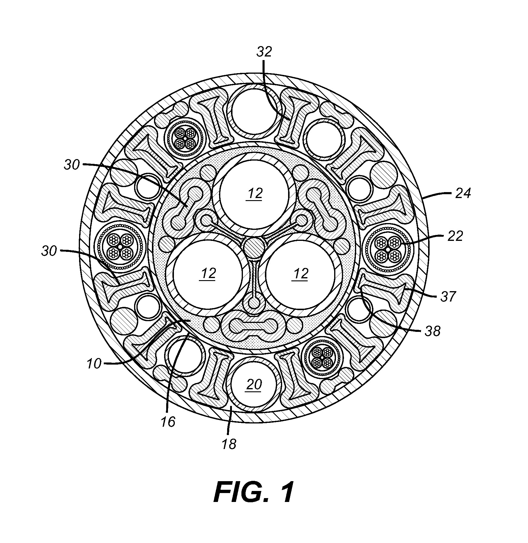
[0005]FIG. 1 illustrates a cross-section of a preferred embodiment of an umbilical according to the present inventions. A preferred embodiment of the present invention comprises an inner section 10 comprising at least two inner tubes 12. In one preferred embodiment, the inner section comprises at least three inner tubes arranged in a triangular configuration wherein a composite fiber element is positioned between each pair of adjacent inner tubes, as illustrated in FIG. 1. In another preferred embodiment, the inner section has a circular cross sectional area, as shown in FIG. 1. This embodiment further comprises a composite fiber element 30 positioned between the two inner tubes and a composite tape 16 surrounding the inner section. In the preferred embodiment shown in FIG. 1, the inner tubes 12 are positioned beside each other.

[0006]A preferred embodiment of the invention further comprises an outer annular section 18 surrounding the composite tape and comprising at least one outer ...


PUM

PropertyMeasurementUnit
electrically conductiveaaaaaaaaaa
transmissionaaaaaaaaaa
cross sectional areaaaaaaaaaaa

Abstract

The present inventions relate generally to umbilicals comprising at least one inner tube and at least one composite fiber element to provide greater resistance to radial compressive forces. Such umbilicals may be used in subsea hydrocarbon production applications.

Description

PRIORITY INFORMATION[0001]This application claims the benefit of U.S. Provisional Application No. 60 / 625,858, filed on Nov. 8, 2004.FIELD OF INVENTION[0002]The present inventions relate generally to umbilicals comprising at least one inner tube and at least one composite fiber element to provide greater resistance to radial compressive forces. Such umbilicals may be used in subsea hydrocarbon production applications.BACKGROUND OF THE INVENTION[0003]Umbilical cables are used to supply power and / or control signals from a topside structure such as a platform to equipment located subsea, such as a remotely operated vehicle “ROV”. Due to increased operating / installation depths of umbilical systems, umbilicals are typically subjected to increasingly higher levels of radial compression forces, e.g. by installation equipment during the actual installation process. The present inveniton relates to the use of composite fiber beam elements and / or composite taping layers and / or composite fibers...

Claims


Application Information

Patent Timeline
Patent Type & Authority Patents(United States)
IPC IPC(8): G02B6/44H01B7/00
CPCG02B6/4416Y10T428/2933G02B6/44H01B7/00H01B7/14H01B11/22
Inventor CHARTIER, ANDREGAHM, PAUL
Owner OCEANEERING INTERNATIONAL
Why Eureka
Try Eureka