Carpentry trim marking gage

a carpentry trim and marking technology, applied in the field of carpentry trim installation, can solve the problems of insufficient satisfaction of the desired purpose of the prior adjustable gages, a very time-consuming and wasteful process, etc., and achieve the effect of facilitating the installation of a casing on the jamb and making intersecting guidelines

Inactive Publication Date: 2007-07-10
DOWDAKIN WILLIAM J
View PDF11 Cites 22 Cited by
  • Summary
  • Abstract
  • Description
  • Claims
  • Application Information

AI Technical Summary

Benefits of technology

[0011]The invention provides an adjustable carpentry trim gage, having a scribing block adjustably attached to a guide block. The guide block includes a guide surface, adapted to be placed against a jamb. The scribing block includes a scribing surface along which a scribing instrument, such as a pencil or an awl, can be drawn to mark guidelines on the jamb, to facilitate installation of a casing on the jamb. The position of the guide block with respect to the scribing block is adjustable to allow the position of the scribing surface on the scribing block, with respect to the guide surface on the guide block, to be set in such a manner that the scribing surface will indicate a desired reveal on the jamb, when the guide surface is bearing against the jamb. The scribing surface extends beyond the maximum reveal setting of the gage, in a direction parallel to the face of the jamb against which the guide surface is bearing, to facilitate making intersecting guidelines indicating corners of the casing.

Problems solved by technology

Because these blocks were not adjustable to accommodate the variations and differences described above, it was necessary to continually re-cut the blocks, or cut a separate block for each window or door.
This is obviously a very time consuming and wasteful process.
None of these prior adjustable gages are entirely satisfactory for the desired purposes, however.

Method used


Image

  • Carpentry trim marking gage
  • Carpentry trim marking gage
  • Carpentry trim marking gage

Examples


Embodiment Construction

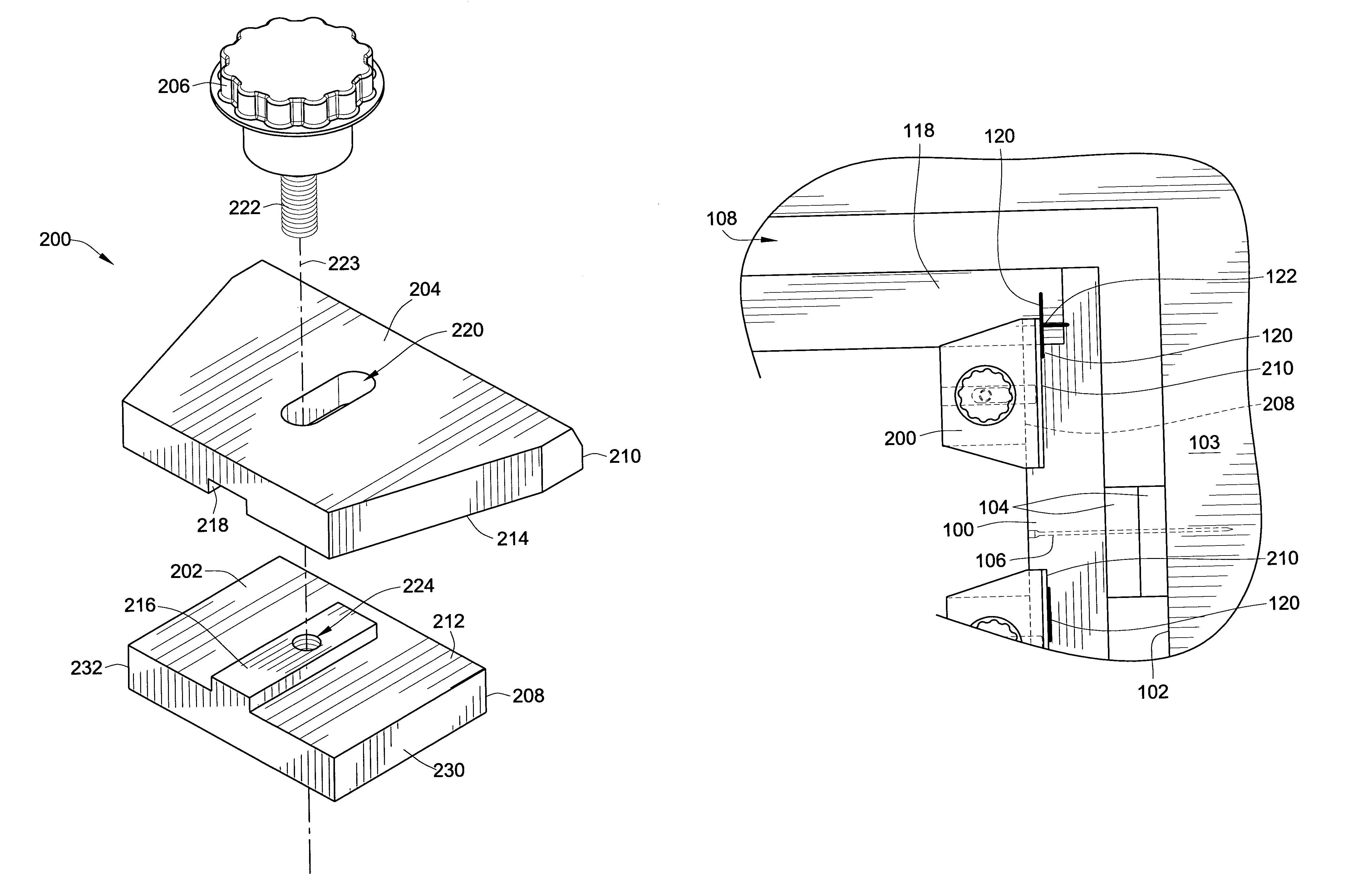
[0019]FIG. 5 shows an exemplary embodiment of a trim marking gage 200, according to the invention, having a guide block 202, and a scribing block 204, adjustably attached to one another by an adjustment knob 206. FIGS. 6 and 7 show a top and a bottom view, respectively, of the assembled gage 200. The guide block 202 includes a guide surface 208, extending along one edge of the guide block 202. The scribing block 204 includes a scribing surface 210 that is oriented parallel to the guide surface 208.

[0020]Mating surfaces 212, 214, respectively, of the guide block 202 and scribing block 204 include alignment features that orient and guide the scribing surface 210 parallel to the guide surface 208. Specifically, protruding from the mating surface 212 of the guide block 202 is an elongated key 216, which extends in a direction perpendicular to the guide surface 208. The elongated key 216 slidingly engages an elongated slot 218, in the mating surface 214 in the scribing block 204. The elo...


PUM


Abstract

An adjustable carpentry trim gage includes a scribing block adjustably attached to a guide block. The guide block includes a guide surface, adapted to be placed against a jamb. The scribing block includes a scribing surface along which a scribing instrument, such as a pencil or an awl, can be drawn to mark guidelines on the jamb, to facilitate installation of a casing on the jamb. The position of the guide block with respect to the scribing block is adjustable to allow the position of the scribing surface on the scribing block, with respect to the guide surface on the guide block, to be set in such a manner that the scribing surface will be placed to indicate a desired reveal on the jamb, when the guide surface is bearing against the jamb. The scribing surface extends beyond the maximum reveal setting of the gage, in a direction parallel to the face of the jamb against which the guide surface is bearing, to facilitate making intersecting guidelines indicating corners of the casing.

Description

CROSS-REFERENCE TO RELATED PATENT APPLICATIONS[0001]This patent application claims the benefit of U.S. Provisional Patent Application No. 60 / 569,748, filed May 10, 2004, the entire disclosure of which is incorporated herein by reference.FIELD OF THE INVENTION[0002]This invention relates to installing carpentry trim around a window or a door, and more particularly to methods and tools for marking a jamb of a window or door, to facilitate installation of a casing trim around the window or door.BACKGROUND OF THE INVENTION[0003]As shown in FIG. 1, windows, doors, medicine cabinets, and the like, typically include an outer frame, commonly called a jamb 100, which is installed into a rough opening 102 in a wall 103, by installing a pair of wedge shaped shims 104 between the outside of the jamb 100 and the inner surface of the rough opening 102, and driving one or more finishing nails 106 through the jamb 100 and shims 104, and into framing of the wall 103 that defines the rough opening 10...

Claims


Application Information

Patent Timeline
Patent Type & Authority Patents(United States)
IPC IPC(8): G01B5/14E04F21/00
CPCA47G27/0487E04F21/0007E04F21/0015
Inventor DOWDAKIN, WILLIAM J.
Owner DOWDAKIN WILLIAM J
Why Eureka
Try Eureka